
User's Manual

30
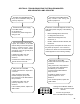
SECTION D: TROUBLESHOOTING THE
POWER SUPPLY
Turn off the power to the module,
disconnectthe18-pinECU
connector.
Checkforhighresistance
(corrosion, wire/connector damage
or improper termination) of the
power lines, resulting in a high
voltage drop across the lines.
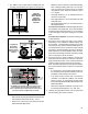
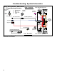
Measure the voltage under load by
placing a load such as a type 1157
brake light bulb between the Ignition
Power pin and Ground pin of the
ECUconnector,whilethelampisin
place.
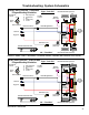
With ignition power to the trailer,
measure the voltage between the
Ignition Power (pin 6) and Ground
(pin18)oftheECUconnector.
Repeat the voltage measurement
with brake lamp power to the trailer,
betweentheBrakeLampPower
(pin12)andtheGround(pin18)of
theECUconnector.
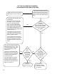
The operating range of the module
is8.0-32.0VDC.Verifythatthe
voltage drop measurements are no
lessthan1.0VDCfromthevehicle
voltage at both the ignition and
brake power inputs.
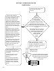
With a volt/ohm meter, check
thepowerandgroundwiring.Look
for corroded or damaged wires or
connectors.
If repairs are made, rerun the
power-upsequence.Goto
Section A.
If proper loaded and unloaded
voltageismeasuredattheECU
connector, and no corrosion or
damage is found on the wiring,
connectorsorECU,replacethe
module.
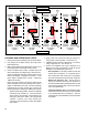
With a volt/ohm meter, check the
powerandgroundwiring.Lookfor
corroded or damaged wire or connectors.
If repairs are made, rerun the power‑up
sequence.GotoSectionA.
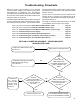
With
ignition
power to the
trailer, measure
the voltage between
the ignition Power pin and the
GroundpinoftheECUconnector.
Repeat the voltage measurement with
brake lamp power to the trailer, and between the
BrakeLampPowerpinandtheGroundpinoftheECU
connector.
The operating range of the module is
8.0-32.0VDC.Canyouverifythat
measurementsfoundareequal
to the vehicle voltage (within
1VDC)atboththe
ignition and brake
power
inputs?
NO
YES
Measure the loaded
voltage across a type
1157 brake light bulb.
LookingintoTABS-6Advancedmodule
WireHarness,ECUConnectorMeasure:
Pin6(IgnitionPower)toPin18(ground)
andPin12(BrakeLightPower)to
Pin18(ground).