
User's Manual

29
SECTION C: TROUBLESHOOTING THE TRAILER‑MOUNTED
ABS INDICATOR LAMP CIRCUITRY
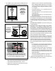
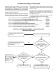
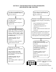
The trailer‑mounted ABS indicator
lamp did not illuminate during the
power-upsequence.
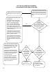
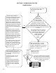
The trailer‑mounted ABS indicator
lamp remains “ON” during the
power-upsequence.
Troubleshoot the power supply
to the ABS module.
GotoSectionD.
Continueifthepowerandground
wiringareOK.
Turn off the power to the module.
Inspect the condition of the ABS
indicator lamp, connector and ground.
Using a volt/ohm meter, verify
continuity from the trailer chassis
ground(pin18)tothegroundpinof
the indicator lamp.
If repairs are made, rerun the
power-upsequence.Goto
Section A.
Continueiftheindicatorlampand
groundwirecheckoutOK.
DetermineifamoduleDiagnosticTrouble
Code(DTC)existsusinganyofthefollowing
methods:
• Blinkcodediagnostics,Section20,
• PCdiagnostics,Section23,
• TrailerRemoteDiagnosticUnit,
Section23,or
• Bendix
®
Trailer Information Module, also
Section23.
IfDTC(s)exist,andrepairsaremade,rerun
thepower-upsequence.GotoSectionA.
ContinueifnoDTCsarefoundandtheABS
module appears to be functioning normally.
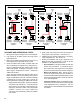
With power off to the ABS
module,disconnectthe18-pinECU
connector.
Verify continuity from the ABS
indicator lamp pin (pin 5) of the
ECUconnectortotheABSindicator
lamp connector.
If repairs are made, rerun the
power-upsequence.Goto
Section A.
If the condition persists, replace the
ABS module.
With power off to the ABS
module,disconnectthe18-pinECU
connector.
Usingavoltmeter,verifythatthere
is not a short to the Vbat between
theABSWLpinoftheECU
connector and the ABS indicator
lamp connector.
If repairs are made, rerun the
power-upsequence.Goto
Section A.
If the condition persists, replace the
ABS module.
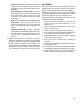
18
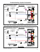
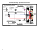
LookingintotheBendix
®
TABS‑6
™
AdvModule18-pinConnectorPigtail
Harness.
Pin18isthegroundpin.
Pin 5 is the ABS indicator lamp pin.