
User's Manual

21
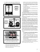
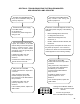
1. The TABS‑6 Adv module shall be installed with the
followingconsiderations(seeFigures16through18):
5°
5°
VERTICAL
ORIENTATION
(ROLL ANGLE)
MUST BE
WITHIN FIVE
DEGREES OF
VERTICAL
FIGURE 16 ‑ INSTALLATION ON TRAILER (VERTICAL)
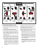
10°
10°
Driving
Direction
Longitudinal
Orientation
(Pitch Angle)
Must be within
Ten Degrees of
Vertical
FIGURE 17 ‑ INSTALLATION ON TRAILER (LONGITUDINAL)
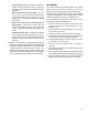
The TABS-6 Adv module must be located no more
than 40 inches from the mid-point between the
axles, and within two inches from the center line of
the trailer (unless congured for an offset).
10°
10°
± 40" (1 m) from mid-point between the axles
± 2" (5 cm)
from center
of trailer
FIGURE 18 ‑ INSTALLATION ON TRAILER (CENTER LINE)
• With exhaust port facing downward and unobstructed
withsignicantfreespacebelow(>1inch).
• Within±40"ofthecenteroftheaxle(s)forproper
balanced brake applications.
• Within ± 2" from the center line of the trailer (default).
Note: a left/right offset greater than ± 2" may have
been programmed in the ECU and can be veried
using Bendix ACom diagnostic software (version
6.1 or higher).
• Yaw angle shallbe ± 10°as measured fromthe
center line of the trailer.
• Pitchangleshallbe±10°asmeasuredfromaat
horizontal plane.
• Roll angle shall be within ± 5° as measured from a
athorizontalplane.
For tank‑mount modules:Installthenipplettinginto
the modulator‑valve supply port. Then rotate the entire
assemblyintothetankportuntilsecure.Over-torquing
of the tank nipple could cause damage to the valve
body.
For frame‑mount modules:Torquethemountingnuts
to180-220in-lbs.
2. Reconnect all air hoses and plugs to the module.
Depending on the installation, additional plugs may
be necessary. Thread sealant products that contain
Teonmaybeused,howeverthreadsealanttapeisnot
recommended as there is a potential for tape material
entering the valve and affecting the valve’s operation.
Make certain that no thread sealant enters the valve.
Allairhosesandttingsshouldbecheckedforleaks
prior to returning the vehicle to service.
3. Reconnect the ECU power, auxiliary if present and
wheelspeedsensorelectricalconnectorstotheECU.
Apply a moderate amount of non‑conductive electrical
grease to each connector pin before reconnecting.
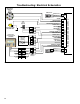
Note:Thewheelspeedsensorsmustfollowtheorienta‑
tionofthemoduleasshowninFigure19forxedaxle
trailers.
• Itisnecessarytoxthewheelspeedsensorsto
the orientation of the lateral acceleration sensor for
plausibility checks between the sensors.
• If the wheel sensor location does not match the
orientation of the Bendix
®
TABS‑6
™
Adv module
shown in Figure 19, a Diagnostic Trouble Code
(DTC)willbegeneratedandtheABSindicatorlamp
will be illuminated.
• Refer to the large label inside the connector cover
forwheelspeeddesignation,“S-C”and“S-D”.
4. Leakage and OperationalTests must be performed
before returning the vehicle to service.