
User's Manual

19
How the Bendix
®
TRDU
™
Tool Operates
WhentheTRDUtoolispluggedintotheadapter—andthe
adapter/TRDUtoolisinstalledbetweenthetrailerconnector
andtheJ560connectorofthetowingvehiclethathasthe
ignitionon—alltheLEDswillilluminate,andthegreen
LEDwill ash4 timesto indicatecommunications have
been established.
IftheABSECUhasnoactiveDiagnosticTroubleCodes
(DTCs),onlythegreenLEDwillremainilluminated.
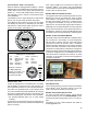
IftheABSECUhasat leastone activeDTCtheTRDU
tooldisplaystherstDTCbyilluminatingtheredLEDs,
indicating the malfunctioning ABS component and its
locationonthevehicle.(SeeFigure13.)
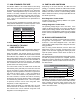
FIGURE 13 ‑ THE BENDIX
®
TRDU
™
TOOL DISPLAY
LED Diagnostic Trouble Codes
VLT- Power
ECU- ABSController
SEN- WheelSpeed
Sensor
MOD1- Modulator1
MOD2- Modulator2
MOD3- Modulator3
LFT- Left
RHT ‑ Right
ADD- Additional
ODO- Odometer
Example:IftheDTC
is "Right Additional
Sensor",theTRDU
™
tool
will display one green
andthreeredLEDs
LEDs
Green
VLT
Blue
ODO
All
others
are
Red
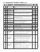
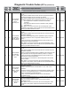
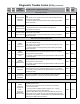
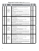
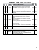
FIGURE 14 ‑ DIAGNOSTIC TROUBLE CODES USING THE
BENDIX
®
TRDU
™
TOOL
IftherearemultipleDTCsontheABSsystem,theTRDU
tool willdisplay one DTCrst, then once thatDTC has
been repaired and cleared, the next code will be displayed.
TheTRDUtoolrepeatedlyblinksoutthemileagestored
once communications have been established. By counting
thesequenceofblinksand/orstrobesontheblueLED,the
odometerreadingisgiven.SeeSection10formoredetails.
• VLT (Flashing indicates either over- or under-voltage
condition)
TopinpointtherootcauseandtoensurethesystemDTCis
properlycorrectedthersttime,additionaltroubleshooting
may be necessary.
Note:WhenaTRDUtoolisconnectedtoasystemwith
a Bendix
®
TABS‑6
™
Adv module, and has established
communications,theECUwillusetheABSindicatorlamp
toblinkcodesforallactiveDTCs.
Bendix TRDU Tool Reset Function
The magnetic reset switch is located by the letter "B" in the
BendixlogoonthetopoftheTRDUtool.Whenamagnet
(with minimum of 30 gauss) is held over theswitch for
lessthan6secondsthe"clearDTCs"commandissent.
(If a magnet is not available, you may use a spare wheel
speedsensor,sinceitsinternalmagnetwillbesufcient.)
Additionally, it is recommended at the end of any inspection
that the technician switches off and restores the power to
theABSECU,andthenre-checkstheABSindicatorlamp
andTRDUtooltoseeiftheyindicateanyremainingDTCs.
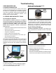
Bendix
®
Trailer Information Module
The Bendix Trailer Information Module is a display device
that combines the functionality of system diagnostics
with the ability to display and store other trailer‑related
information of value to an operator, driver or workshop.
Maximumbenetisobtainedfromthemodulefunctionality
when it is mounted on the trailer so that it is able to record
events that occur during driving. Alternatively, it may also be
used as a workshop tool to access diagnostic information or
tocheckthecongurationorrunaninstallationtest.Inboth
casesthemoduleisconnectedtotheJ19395VTI(CAN)
connection of the auxiliary connector which supplies the
necessary information.
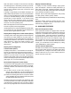
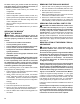
FIGURE 15 ‑ TRAILER INFORMATION MODULE
ADDITIONAL SUPPORT AT
www.bendix.com
For the latest information, and for free downloads of literature
and the Bendix
®
ACom
®
diagnosticssoftware,anditsUser
Guide, visit the Bendix website at www.bendix.com.
Bendix Technical Assistance Team
For direct personal technical support, call the Bendix
technical assistance team at 1‑800‑AIR‑BRAKE(1-800-
247-2725),MondaythroughFriday,8:00a.m.to6:00p.m.
EST.
Alternatively, you may e‑mail the Bendix Tech Team at:
techteam@bendix.com.