
User's Manual

2
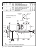
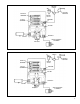
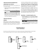
FIGURE 2 - MC-12
™
MODULATOR TRAILER SYSTEM WIRING SCHEMATIC
Seven Conductor Antilock Wire Gauge
Pin (Wire Connector Wire Single/
Connector No.) Letter Color Lamp and Signal Circuits Dolly Double Triple
1 1 C White Ground Return To Towing Vehicle 12 10 8
2 2 - Black Clearance, Side Marker and Identification Lamps 12 12 12
3 3 - Yellow Left Hand Turn Signal and Hazard Signal Lamps 12 12 12
4 4 - Red Stop Lamps 10 10 10
5 5 - Green Right Hand Turn Signal and Hazard Signal Lamps 12 12 12
6 6 - Brown Tail, Clearance, Side Marker and License Plate Lamps 12 12 12
7 7 B* Blue Auxiliary, Dome, Etc. or constant Antilock power 12 12 12
4 9 A Red Antilock Power From Stop Lamp 10 10 10
- 8 D Yellow Trailer Mounted Status Light 14/16 14/16 14/16
- 10/11 N/P - Wheel Speed Sensor 16/18 16/18 16/18
- 12/13 M/L - Wheel Speed Sensor 16/18 16/18 16/18
* Antilock Connector Pin B is an option and is used to provide constant power to the MC-12
™
modulator during trailer operation.
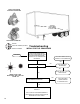
Trailer
Mounted
Status
Indicator
Marker Marker
Marker Marker
Clearance
Clearance
Wheel
Speed
Sensor
Marker
Marker
Rear 7 Pin
Connector
Plug (See
Note)
Wheel
Speed
Sensor
CI/Directional
CI/Directional
Stop & Tail
Stop & Tail
License Plate
Note:
The rear 7 pin connector plug is for Dolly operations for Doubles & Triples
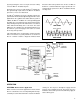
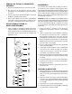
To Pin “G” on
MC-12
™
Modulator
Connector
To Power Side of
Tractor Ignition
Tractor Electrical
Relay
Tractor Dash Mounted
Trailer Antilock Status
Lamp
The relay illustrated to the right is used when
a tractor, dash mounted status lamp for the
trailer antilock system is desired. Like the
trailer mounted status lamp, this is an option
and is not required.