
Troubleshooting guide


83
For more information, visit www.bendix.com or www.foundationbrakes.com • 1-800-AIR-BRAKE (1-800-247-2725)
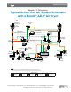
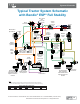
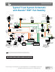
Typical Tractor System Schematic
Typical Tractor System Schematic
with Bendix
with Bendix
®
®
ESP
ESP
®
®
Full Stability
Full Stability
Notes:
The color coding of the brake system schematic follows TMC Recommended Practice #423.
Air disc & drum brake actuation combined on a single axle are shown for pictorial purposes only.
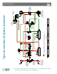
C
S
Front
Axle Reservoir
Rear
Axle Reservoir
E-8P
®
/ E-6
®
Brake Valve with
BVA-85
™
Brake
Valve Actuator
MV-3
®
Control Valve
DC-4
®
Double
Check Valve
TCS-9000
™
Valve
YAS-60
™
Yaw
Rate & Lateral
Acceleration
Sensor
QR-1C
®
Quick
Release
Valve
AD-IS
®
Air Dryer
WS-24
™
Wheel
Speed Sensor
Rear Axle
Module (RAM)
with ATR-6
™
Traction
Relay Valve
Hose
Couplings
WS-24
™
Wheel
Speed Sensor
Tu-Flo
®
550/
Tu-Flo
®
750
BA-921
®
/ BA-922
®
Air Compressor
PP-5
™
Control
Valve
(for pre-trip
inspection)
TP-3DC
™
Tractor
Protection
Valve
EC-60
™
Electronic
Controller
Advanced
ADB22X
™
Air Disc
Brake
ADB22X
™
Air
Disc
Brake
Low Pressure
Indicator
To Accessories
Antilock
Modulator
(4 places)
ATR-6
™
Traction
Relay
Valve
SAS-60
™
Steering
Angle
Sensor
Bendix Extended
(ES)
™
Drum Brake
with Automatic Slack
Adjuster and Service
Chamber
Bendix Extended
(ES)
™
Drum Brake
with Automatic Slack
Adjuster and Service
Chamber
Stop Light Switch
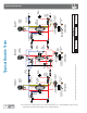
Control
Supply
Antilock
Modulator
Charging Primary Secondary Park (Supply) Parking (Control) Accessories
TRUCKS AND TRUCK TRACTORS:
System Schematic
©2014 Bendix Commercial Vehicle Systems LLC • All Rights Reserved