
Troubleshooting guide


65
For more information, visit www.bendix.com or www.foundationbrakes.com • 1-800-AIR-BRAKE (1-800-247-2725)
Air Brake System Troubleshooting Tests (continued)
TEST 3
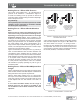
Pressure Modulator Valve and Traction Control Valve Chuff Test
FULL PRESSURE, ENGINE STOPPED, PARKING BRAKES RELEASED
;
OK
;
Not
OK
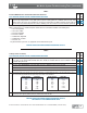
1. Make and hold brake application. When ignition power is applied, each modulator solenoid is briefl y energized. If the air
system is fully charged and the service brake pedal is depressed during ignition, the modulator creates a single, sharp
audible “chuff” of air pressure. The modulators are energized in a certain pattern, as follows: right front, left front, right rear,
left rear. This test is performed only when the vehicle is stationary (if the vehicle moves the chuff test will not be performed).
NOTE: The Bendix
®
EC-60
™
controller will perform a PMV chuff test on all installed modulators in the following order:
1. Steer Axle Right PMV
2. Steer Axle Left PMV
3. Drive Axle Right PMV
4. Drive Axle Left PMV
5. Additional Axle Right PMV
6. Additional Axle Left PMV
7. Drive Axle TCV
The pattern will then repeat itself. See appropriate Service Data Sheet for repairs.
MAKE ALL NECESSARY REPAIRS BEFORE PROCEEDING TO TEST 4.
TEST 4
Leakage service air delivery
FULL PRESSURE, ENGINE STOPPED, PARKING BRAKES RELEASED
;
OK
;
Not
OK
1. Make and hold an 80-90 psi brake application. This can be accomplished by using the Bendix
®
BVA-85
™
brake valve actuator.
If the vehicle is not equipped with a BVA-85 brake valve actuator, an assistant should be used to maintain a constant
application during these tests.
2. Allow pressure to stabilize for 1 minute; then begin timing for 2 minutes while watching the dash gauges for a pressure drop.
A. Pressure Drop: Single Vehicle (A 4 psi drop within 2 minutes is allowable for either service reservoir)
B. Pressure Drop: Tractor/Trailer (A 6 psi drop within 2 minutes is allowable for either service reservoir)
C. Pressure Drop: Tractor/2 Trailers (An 8 psi drop within 2 minutes is allowable for either service reservoir)
3.
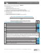
Check brake chamber push rod travel (refer to chart below for the CVSA Max allowable Stroke). With the parking brakes released
and service brakes applied with 80 to 90 psi of air pressure to the service chambers.
4. Check the angle formed between the brake chamber push rod and the slack adjuster arm. It should be equal to or slightly
less than 90° in the applied position (80-90 psi) and the same across the axle.
MAKE ALL NECESSARY REPAIRS BEFORE PROCEEDING TO TEST 5;
SEE CHECKLIST 4 FOR COMMON CORRECTIONS.
Brake Chamber
Type
CVSA Max.
Allowable Stroke
12 1-3/8”
12L 1-3/4”
16 1-3/4”
16L 2”
20 1-3/4”
20L 2”
20L3 2-1/2”
Brake Chamber
Type
CVSA Max.
Allowable Stroke
24 1-3/4”
24L 2”
24L3 2-1/2”
30 2”
30L 2-1/2”
36 2-1/4”