
Troubleshooting guide


60
For more information, visit www.bendix.com or www.foundationbrakes.com • 1-800-AIR-BRAKE (1-800-247-2725)
The length of the slack adjuster lever arm and the
size or effective area of the brake chamber acting
on the slack adjuster are the two variables altered
to meet braking requirements. The product of the
effective area of the brake chamber and the length of
the slack adjuster arm is expressed as the “AL” factor.
When multiplied by the 60 pounds of air pressure used in
making brake calculations, the “AL” factor determines the
torque on the brake camshaft.
For example: If a brake chamber having an effective area
of 16 square inches is acting on a slack adjuster within an
arm length of fi ve inches, the “AL” factor is 80. The actual
torque on the brake camshaft, therefore, is the “AL” factor
(80) multiplied by the air pressure used in making brake
calculations (60), or 4,800 inch pounds.
Bendix
®
Air Disc Brakes
Bendix
®
air disc brakes (ADB) are “fl oating caliper”
pneumatic disc brakes for use as the foundation
braking on all axles of heavy-duty commercial vehicles
and trailers. Air disc brakes are easier to service than
traditional S-Cam brakes. Air disc brakes are available in
models with or without spring brakes.
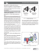
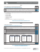
The function of the ADB is to convert the air
pressure applied when the driver applies the brakes
into braking force against the rotor on the vehicle
wheel. This is done by the application of air from the foot
brake or relay valve entering the brake chamber, causing
the plate to move the push rod outwards. The push rod
exerts force on the lever (see Figure 17) and this force is
transferred and multiplied as it turns around the eccentric
bearing. The bearing and the connected actuating beam
move outward, overcoming the force of the two return
springs. The force is then transferred to the two threaded
tubes, tappets, and fi nally to the inner and outer brake
pads.
Air Brake System Balance
The air brake system is one of the most important
safety systems on a vehicle. Air brake systems
are carefully designed with valves, tubing, or hoses,
etc., selected to result in balanced vehicle braking
performance – where all the brakes apply as close to
simultaneously as possible and with the desired amount
of force. Proper vehicle maintenance will result in the
original performance being retained, emphasizing why
component replacement and general brake system
maintenance are critical. Routine system maintenance
operations should be performed with this in mind.
Two major areas that we cover here are:
I. Pneumatic (Air) and II. Mechanical.
I. Pneumatic (Air) Systems
General
An ideal or balanced braking system is one in which
the brake pressure reaches each actuator as close
to simultaneously as possible and at the same
pressure level (and at an appropriate level to achieve
torque balance with respect to the axle’s loading).
We recommend downloading the BW1555 Air Pressure
Balance & Threshold Pressure Tests worksheet from the
Literature Center at www.bendix.com.
Transmission Time
Vehicle manufacturers must comply with the
air system timing requirements of government
regulations (e.g., U.S. FMVSS 121, Canadian CMVSS
121). In establishing this performance, manufacturers
carefully select tubing and hose sizes. Air application
and release performance is partially dependent upon
the size and volume of chambers, vehicle weights, and
locations of the valves and chambers, or distance the air
must travel. Performance is engineered into the vehicle
by the manufacturer. The role of the vehicle owner and/
or mechanic is to preserve that pneumatic performance.
Here are a few tips to assist in that effort.
Tubing
When replacing tubing or hoses, always replace
with Department of Transportation(DOT)- or Society
of Automotive Engineers (SAE)-approved tubing of
the same size. These sizes have been determined by
the vehicle manufacturer to obtain desired performance.
If copper tubing is used, always make sure to ream
and de-burr the tubing after cutting. Check carefully for
restrictions such as kinking or bending, and make sure
tubing and hoses are properly supported. Use the proper
size fi ttings and make certain they are not restricted. As
a rule, do not replace straight fi ttings with elbows. Note: It
takes as much time for air to fl ow through an elbow fi tting
as through six to seven feet of tubing or hose.
Air Brake System Balance: Pneumatic Systems