
Troubleshooting guide


58
For more information, visit www.bendix.com or www.foundationbrakes.com • 1-800-AIR-BRAKE (1-800-247-2725)
Key Takeaway:
The quantity of air acting on the piston or diaphragm
does not affect the force developed. The only factors
involved are the air pressure and the area of the piston
or diaphragm on which the air pressure is acting. This
means that we can control the force applied by the
braking system by controlling the air pressure
.
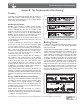
The pressure exerted by compressed air is not only
developed in all directions, but it is also equal in all
directions. The compressed air in a reservoir exerts
pressure equally in all directions against the entire inside
surface of the reservoir (the pressure of the compressed
air being overcome by the mechanical strength of the
reservoir walls). Similarly, the force developed by the air
pressure acting on one side of a piston or a diaphragm
may be overcome by an opposing force acting on
the opposite side, and the opposing force may be
compressed air or it may be mechanical. If the opposing
forces are equal, a balanced condition is reached and
there is no movement of the piston or diaphragm. If the
opposing forces are not equal, the piston or diaphragm
will move, if possible, to assume a position where the
opposing forces are equal. See Figure 13.
This law of balanced pressures and forces is the
basic principle governing the design and operation
of the control and actuating devices in an air brake
system.
The Fundamentals of Compressed
Air Brakes
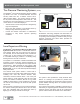
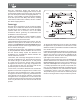
Compressor, Reservoir and Brake Valve
In an air brake system, the compressor supplies the
compressed air for brake operation by taking free air
and compressing it to 100-120 psi (Maximum pressure
in an air brake system is generally 150 psi).
The compressed air passes from the compressor into
the reservoir and the air brake system. There, the air
and its energy are stored until needed by the driver for
a brake application.
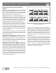
Service Brake System
When the brake valve is operated by the driver, air fl ows
to the chambers where its energy is transformed into
the mechanical force and motion necessary to apply the
brakes.
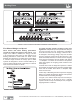
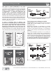
FIGURE 15 - BRAKING FORCES-EFFECT OF BRAKE CHAMBER SIZE
Clamp Ring Brake Chamber
or Rotochamber
6 9 12 16 20 24 30 36 50*
Effective Area of
Diaphragm (square in.)
6 9 12 16 20 24 30 36 50
Pounds of Force
Developed @ 30 psi
180 270 360 480 600 720 900 1090 1500
Pounds of Force
Developed @ 60 psi
360 540 720 960 1200 1440 1800 2160 3000
Force Developed by Various Size
Brake and Rotochambers at 30 and
60 psi.
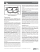
FIGURE 14 - BRAKING FORCES-EFFECT OF AIR PRESSURE
Air Pressure
(psi)
5 10203040 60 80 100
Developed
Force
(psi)
120 240 480 720 960 1440 1920 2400
Typical ‘Type-24’
Brake Chamber
Having an Effective
Diaphragm Area of
24 Square Inches.
Compressed Air Brakes
* Rotochamber only