
Troubleshooting guide


53
For more information, visit www.bendix.com or www.foundationbrakes.com • 1-800-AIR-BRAKE (1-800-247-2725)
Now let’s reintroduce weight and speed into the
comparison. If the same stopping power is used, a 5,000
pound vehicle needing only 30 feet to stop from 20 miles
per hour will require 18 times the stopping distance – or
540 feet – when loaded to 10,000 pounds and traveling
at 60 miles per hour. Note: Many other factors, including
road surface, brake friction material, and tire condition
also affect stopping distance.
Leverage
Now that we’ve reviewed the forces involved in braking
a vehicle, let’s consider how these forces are developed
and directed to do the braking work. Almost all braking
systems make use of the lever, one of the oldest
mechanical devices governing the transmission and
modifi cation of force and motion.
A lever is an infl exible rod or beam capable of motion
about a fi xed point called a fulcrum, and it is used to
transmit and modify force and motion.
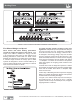
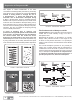
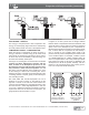
Figure 5 illustrates three simple types of levers. The only
difference among them is the location of the fulcrum in
relation to the applied force and the delivered force. All
shapes and sizes of levers used in a typical brake system
are one of these three types.
A simple law governs levers: The applied force multiplied
by the perpendicular distance between the line of force
and the fulcrum always equals the delivered force
multiplied by the perpendicular distance between the
fulcrum and the line of force.
That means, with a leverage arrangement as shown in
view 5(a), an applied force of 100 pounds two feet from
the fulcrum will give a delivered force of 200 pounds
at a point one foot from the fulcrum. With a leverage
arrangement as shown in Figure 5(b), an applied force
of 100 pounds three feet from the fulcrum will lift 300
pounds at a point one foot from the fulcrum.
In both cases, note that the delivered force exceeds the
applied force because the applied force is farther from
the fulcrum than the delivered force. With a leverage
arrangement as shown in Figure 5(c), the delivered force
is the farthest from the fulcrum; therefore, it is less than
the applied force. If the applied force in this case is 300
pounds at a point two feet from the fulcrum, the delivered
force at a point three feet from the fulcrum will be 200
pounds.
To calculate the delivered force of any lever, fi rst multiply
the applied force by its distance from the fulcrum. Then
divide this answer by the distance between the delivered
force and the fulcrum.
In determining the distance at which any force is acting on
a lever, the true length of the lever arm is the perpendicular
distance from the force to the fulcrum, regardless of the
shape of the lever. The lever arm is always measured at
right angles to the direction of the force.
The product of the force acting on a lever, multiplied by the
distance between the force and the fulcrum, is called the
turning moment. When the turning moment relates to a
shaft, it is called torque. The turning moment – or torque
– is usually expressed in inch-pounds, foot-pounds, foot-
tons, etc. The designation depends on whether the force
is measured in pounds or tons, and whether the distance
is measured in inches or feet. For example, a force of
100 pounds acting on a lever arm fi ve inches long would
result in a turning moment or torque of 500 inch pounds.
FIGURE 5 - LEVERAGE
5(a)
5(b)
5(c)
Leverage