DRIVING SAFER DOESN’T HAPPEN BY ACCIDENT. Our nation’s roadways are increasingly busy, and the need has never been greater for solutions to help commercial vehicle drivers respond to the situations they encounter every day – especially in today’s CSA (Compliance, Safety, Accountability) environment. Bendix is leading the way to improved highway safety with an ever-increasing portfolio of road-tested, advanced commercial vehicle technologies that are affordable and effective.
The Air Brake Handbook For more information, visit www.bendix.com or www.foundationbrakes.
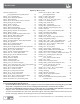
Device Index Alphabetic Device Index AutoVue® by Bendix CVS Lane Departure Warning (LDW) System . . . . . 50 Bendix® A-18™ Controller Assy . . . . . . . . . . . . . . 44 Bendix® ACom® Diagnostic Software . . . . . . . . . . . 48 Bendix® Brand Actuators. . . . . . . . . . . . . . . . . . 20 Bendix® AD-2®, AD-9®, AD-9si™, AD-IP® Air Dryers . . . . 13 Bendix® AD-IS® Air Dryer Module . . . . . . . . . . . . . 13 Bendix® AD-SP® Air Dryer . . . . . . . . . . . . . . . . . 15 Bendix® AF-3™ In-line Air Filter. . .
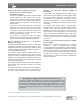
Handbook Section Index How to use the Air Brake Handbook This twelve-section handbook provides an introduction to the use and operation of Bendix air brake systems and devices. Components are introduced and shown with typical system diagrams to depict where they are used. As new components are introduced and their function explained, they gradually build up to a complete functioning air brake system reflected in the schematics at the close of this handbook.
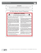
General Precautions IMPORTANT The systems presented in this manual are intended for illustrative purposes only and are not intended to be used for actual vehicle piping. Air Brake System General Precautions GENERAL SAFETY GUIDELINES WARNING! PLEASE READ AND FOLLOW THESE INSTRUCTIONS TO AVOID PERSONAL INJURY OR DEATH: When working on or around a vehicle, the following guidelines should be observed AT ALL TIMES: ▲ Park the vehicle on a level surface, apply the parking brakes and always block the wheels.
:KHQ
Introduction Section 1: An Introduction Air Supply The vehicle’s compressor takes in filtered air — either at atmospheric pressure from the outside or already at an increased pressure from an engine turbocharger — and compresses it. The compressed air is delivered to the air dryer where water and a small amount of oil is removed. The air then travels into the air reservoirs (“air tanks”).
Introduction, continued Electronically-Controlled Braking (continued) • Bendix® Electronic Stability Program/ Full Stability Program The ESP®* functionality of the Bendix advanced ABS system responds to a wide range of low- to highfriction surface scenarios including rollover, jackknife and loss-of-control. It is the recommended system for all power vehicles and especially critical for tractors pulling trailers.
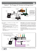
The Charging, Air Treatment and Storage System Section 2: The Charging, Air Treatment and Storage System Traditional Air Charging System To Front Axle To Rear Axle Low Pressure Indicator Note: A threereservoir system is shown here. See below for a system using an integrated air dryer/reservoir.
The Charging, Air Treatment and Storage System: Compressors Bendix Air Compressors The air compressor is the source of energy for the air brake system. Usually driven by the vehicle engine, the air compressor builds the air pressure for the air brake system. The air compressor is typically cooled by the engine coolant system and lubricated by the engine oil supply. (Certain models have self-lubricated and/or air-cooled versions available.) Note: Air compressor shafts can rotate in either direction.
The Charging, Air Treatment and Storage System: Compressors Bendix® SingleCylinder Compressors Bendix® Two-Cylinder Compressors Tu-Flo ® 550 Air Compressor or Tu-Flo ® 750 Air Compressor (exterior view is the same.) BA-921® Air Compressor BA-922® Air Compressor (shown) or DuraFlo 596™ Air Compressor (exterior view is very similar.
The Charging, Air Treatment and Storage System: Compressors 2 4 Discharge Line Length Maintenance Schedule and Usage Guidelines Air Dryer Maintenance Schedule Regularly scheduled maintenance is the single most important factor in maintaining the air brake charging system. Depending on the vehicle’s air use, the table below shows examples of compressors spec’d, and typical discharge line lengths and maintenance intervals. See your compressor and/or air dryer Service Data Sheet for more information.
The Charging, Air Treatment and Storage System: Governors, Etc. Governors and Components The Governor monitors the air pressure in the supply reservoir and operates the compressor unloading mechanism to control whether or not the compressor builds air pressure. Exhaust Port Shown With Breather Valve Installed Bendix ® D-2A™ Governor Bendix ® D-2® Governor The Bendix® D-2® governor is an adjustable pistontype valve. It is available preset to a choice of pressure settings.
The Charging, Air Treatment and Storage System: Air Dryers Integrated Purge Reservoir The Bendix ® PuraGuard® Graphics and Medallion - Indicates the presence of a PuraGuard Oil Coalescing Cartridge Bendix ® AD-9 ® Air Dryer Bendix ® AD-9 ® Air Dryer Cartridge Bendix ® AD-IS® Air Dryer Module Bendix ® AD-IS® Air Dryer Governor Bendix ® AD-IP ® DI Air Dryer (“Drop-in” version) Bendix ® AD-IP ® Air Dryer Cartridge Feedback Line Bendix ® AD-9si™ Air Dryer Bendix ® AD-2®Air Dryer Special Discharge Port
The Charging, Air Treatment and Storage System: Air Dryers Purge Cycles, Purge Volume Bendix® EverFlow® Modules When the air pressure in the supply air tank reaches the required level, the governor makes the compressor stop building air and allows the air dryer’s “purge cycle” to begin. During the purge cycle, the desiccant material is regenerated (its ability to remove water is renewed) by a reversal of the saturation process.
The Charging, Air Treatment and Storage System: Air Dryers Special Use Air Dryers Several Bendix air dryers are available in specialized “Drop-in” versions designed especially for air systems that use either the Holset (Cummins) Type E, or QE, air compressor. These Holset compressors use an unloading system that requires that air pressure remain in the discharge line during the entire unloaded cycle of the compressor. For example, the Bendix® AD-IP® air dryer “Drop-in” version is shown on page 13.
The Charging, Air Treatment and Storage System: Reservoirs, Etc. Reservoirs, Etc. Reservoirs (or “air tanks”) serve the air brake system as a storage tank for compressed air. The reservoir size is selected by the vehicle manufacturer to provide an adequate amount of air for use by the braking system and other control devices.
The Charging, Air Treatment & Storage System: Misc. Components Miscellaneous Components A double check valve is used in the air system when a single function or component must receive air from, or be controlled by, the higher of two pressure sources. An internal disc, or shuttle, moves in response to the higher air pressure and allows the air source to flow out of the delivery port. It is recommended that double check valves are always mounted so that the shuttle (or disc) operates horizontally.
The Control System: Dual Circuit Brake Valves Section 3: The Control System The control system typically consists of: • A foot brake valve and, often, an additional handoperated trailer brake control valve; • Vehicle parking using push-pull hand-operated valves and spring brakes; • Brake actuators or rotochambers, to change the applied air pressure into a push rod force which operates the foundation brakes (air disc, foundation drum brakes, etc.
The Control System: Dual Circuit Brake Valves, continued Note: Brake valve replacements are typically supplied without the foot pedal components. For illustration, full assemblies are shown here.
The Control System: Actuators Actuators During service braking, actuators convert the air pressure being produced by the driver pushing on the brake pedal into a mechanical push rod force acting on the foundation brakes. Air enters the actuator and pressurizes a chamber containing a rubber diaphragm. The air pushes against the diaphragm, pushing against the service return spring and moving the push-plate (and push rod) forward. See the Section 8 for information about the physics behind how actuators work.
The Control System: Foundation Brakes Foundation Brakes: Drum Brakes (aka S-Cam) and Air Disc Brakes S-CAM FOUNDATION DRUM BRAKE AIR DISC BRAKE Brake Chamber Friction Material Rotor Spider Automatic Slack Adjuster Axle CAM Brake Pads Shoe Friction Material Replacement Kit Friction Material Replacement Kit The foundation brake is the actual braking mechanism located at each end of the axle that provides the primary retardation for controlling vehicle speeds.
The Control System: Foundation Drum Brakes Foundation Drum Brakes S-Cam Foundation Drum Brake and Examples of Friction Material Brake Block In an S-Cam type foundation drum brake, the pneumatic system is linked by an air line to the air service and/or spring brake chamber, which is then connected to the arm of a slack adjuster by a push rod and clevis. The slack adjuster is installed on the spline of the forged brake cam shaft.
The Control System: Air Disc Brakes Air Disc Brakes Rotor Brake Chamber Brake Pad Friction Material Bendix ® Air Disc Brake Bendix air disc brakes are a “floating caliper” design for use as a foundation brake on all axles of heavy commercial vehicles and trailers. In terms of performance and ease of service, Bendix® air disc brakes compare favorably to traditional foundation drum brakes. They are available in models with or without a combination spring brake chamber.
The Control System: Slack Adjusters Slack Adjusters Slack adjusters are used on foundation drum brakes to link the brake chamber or actuator and the camshaft. Its arm is fastened to the push rod with a yoke and its spline is installed on the foundation brake camshaft. The slack adjuster transforms and multiplies the force developed by the chamber into a torque which applies the brakes via the brake camshaft.
The Control System: Quick Release, Ratio and Modulating Valves Quick Release, Ratio and Modulating Valves Bendix ® QR-1® Quick Release Valve Quick Release Valves The function of quick release valves is to speed up the exhaust of air from the air chambers. They are mounted close to the chambers they serve.
The Control System: Relay Valves Relay Valves Relay valves are primarily used on vehicles to apply and release rear axle(s) service or parking brakes. When the driver applies the brakes, air travels through the delivery (in this case, signal) line to the relay valve and moves an internal piston down. This closes the exhaust and opens the delivery of air to the brakes.
The Control System: Push-Pull Valves Push-Pull Control Valves Push-pull control valves are most often mounted on the vehicle dash board and are used for a variety of control applications. The Bendix® PP-1® and PP-2™ valves are pressure-sensitive, normally-closed, on/off control valves which automatically return to the exhaust (button out) position when supply pressure is below the required minimum. They may be manually operated to either position when pressure is above the required minimum.
The Control System: Spring Brake Valves Spring Brake Valves The Bendix® SR-1™ spring brake valve is used in dual circuit brake systems and serves two functions: first, during normal operation, it limits hold-off pressure to the spring brakes to 90 or 95 psi. Next, if a loss of pressure occurs in the rear brake service supply, the valve will provide a modulated spring brake application proportional to the driver’s service braking pressure delivered to the front axle.
The Control System: Lever Operated Control Valves Lever-Operated Control Valves The Bendix® TW-2™ and TH-3™ valves are identical in appearance (and similar to the Bendix® TW-1™, TW-3™, and TW-4™ valves) except they have two control valves housed in a single body. These two valves differ by the internal cammed control lever — which for the TW-2 control valve has two lever positions — while the TH-3 valve has three.
The Control System: Additional Valves Additional Control Valves Inversion valves are air-operated control valves and, unlike most control valves, are normally open, (e.g. without control pressure, the supply is common to the delivery). The inversion valve is closed by using air pressure from another source and is primarily used in emergency or parking brake systems which operate with air from an isolated reservoir.
Tractor/Trailer Parking and Emergency Systems Section 4: Tractor Parking, Trailer Charging/ Parking and Emergency Systems The tractor/trailer parking and emergency system typically consists of: • The tractor parking control system; • The trailer parking and emergency system; and • The tractor protection system. See section 12 for system schematics. Park Control Valves The Bendix® PP-DC® park control double check valve is a push-pull, manually operable on/off valve with an integral double check.
Parking and Emergency Systems: Dash Control Valves Dash Control Valves The Bendix® MV-3® dash control module combines the functions of a Bendix® PP-1® control valve and a Bendix® PP-7™ trailer supply valve together into a unified device.
Parking and Emergency Systems:Tractor Protection Valves Tractor Protection Valves The primary function of tractor protection valves (e.g. the Bendix® TP-3® tractor protection valve) is to protect the tractor air brake system under trailer breakaway conditions and/or conditions where severe air leakage develops in the tractor or trailer. In addition, in everyday use, the valve is used to shut off the trailer service and supply lines before disconnecting the tractor from the trailer.
Parking and Emergency Systems: Trailer Spring Brake Valves Trailer Spring Brake Valves Trailer spring brake valves are designed for use in trailer air brake systems. The Bendix® SR-4™ trailer spring brake valve was an earlier design that used a dedicated spring brake reservoir for release of the trailer spring brakes. Note: The valve (superseded by the Bendix® SR-5™ valve)is available for service only, due to changes made in FMVSS 121.
Parking and Emergency Systems Trailer Spring Brake Valves, cont. The Bendix® SRC-7000™ trailer spring brake valve is a reservoir-mounted trailer valve that can control up to six spring brake actuators during parking or emergency applications.
Trailer/Converter Dolly Brakes Section 5: Converter Dolly Brakes Typical components found in a converter dolly brake system are shown in this section.
Trailer/Converter Dolly Brakes, cont. The Bendix® RE-6NC™ (non-charging) relay emergency valve is used in dolly systems and replaces the conventional RE-6® valve. The RE-6NC™ valve is similar to the RE-6® valve but is designed to prevent direct filling of the dolly reservoir through the RE-6NC™ valve. It is generally used in conjunction with the PR-3™ pressure protection and single check valve to provide rapid dolly brake release.
Antilock Braking Systems: Components Section 6: Antilock Braking Systems See section 12 for other system schematics. Bendix® Antilock Braking Systems (ABS) use wheel speed sensors, ABS pressure modulator valves, and an Electronic Control Unit (ECU) to control either four or six wheels of a vehicle. Bendix ECUs are able to optimize slip between the tire and the road surface by monitoring individual wheel turning motion during braking, and adjust (or pulse) the brake pressure at the wheel end.
ABS Components Continued: Truck and Tractor ABS Operation ABS Components, continued • Dash-mounted tractor ABS Indicator Lamp • Service brake relay valve • Dash-mounted trailer ABS Indicator Lamp (used on all towing vehicles manufactured after March 1, 2001) • Optional blink code activation switch • Optional ABS off-road switch.
Truck and Tractor ABS Operation; ATC Right Steer Axle Right Drive Axle Right Additional Axle Driver Left Drive Left Additional Axle Axle Vehicle Axle Naming Convention Left Steer Axle Normal Braking During normal braking, air brake pressure is delivered through the ABS PMV and into the brake chamber. If the ECU does not detect excessive wheel slip, it will not activate ABS control, and the vehicle stops with normal braking.
Advanced ABS Advanced ABS Yaw Stability Yaw stability counteracts the tendency of a vehicle to spin about its vertical axis. During operation, if the friction at the tires is not sufficient to oppose lateral (side) forces, one or more of the tires can slide, causing the truck/ tractor to spin. These are referred to as under-steer or over-steer situations.
Advanced ABS Operation, Features Steering Angle Sensors The sensor enables the Bendix Advanced stability system to capture the driver’s steering input and intervene if a yaw correction is indicated. The sensor also provides the earliest indication of an increase in lateral acceleration leading to a potential roll event, resulting in much higher stability margin when a vehicle is equipped with a steering angle sensor.
Advanced ABS Features Stability System Effectiveness Sense Potential Situations Quickly and Completely Speed Measures the vehicle's velocity Lateral Acceleration Measures the vehicle's tendency to roll Steering Captures the driver's intended direction Brake Demand Accurately supplements the driver Yaw Rate Measures vehicle spin, and compares it to the steering intention and expected rate of turn Bendix® ESP® Stability System Reaction Time and Robustness Multi-Level Sensing Leading indicators ai
Trailer ABS Components and Operation Trailer ABS Components Typical Trailer ABS components are Bendix Electronic Control Units (ECUs) such as: Bendix ® TABS-6™ Trailer ABS • the Bendix® TABS-6™ standard trailer ABS module; • the Bendix® TABS-6™ premium trailer ABS module; • the Bendix® TABS-6™ Advanced (a single channel ABS trailer system) with roll stability control; • the Bendix® TABS-6™ Advanced MC (a multi-channel version of the advanced trailer ABS system) with roll stability; as well as • the Bendi
Trailer ABS Operation and Features, PLC,Troubleshooting Example of 2S/1M Axle Control ABS Trailer Schematic Right “Curb-Side” A - Brake Light Power B - Ignition Power C - NC D - Indicator Lamp E - Ground Bendix ® Versajust ® Automatic Slack Adjuster Control Line Trailer Chassis Harness 7-Pin Connector Ground Ignition Power Supply Line WS Sensor “SR” 5-Pin Connector Bendix ® SB-4™ Spring Brake Trailer ABS Pigtail Harness Bendix ® SR-5™ Trailer Spring Brake Valve Bendix Cyclone DuraDrain® Filtrati
Advanced Trailer ABS Operation and Features Troubleshooting: System Schematics Example of Advanced 4S/2M ABS Trailer Schematic Ground Ignition A - Brake Light Power B - Ignition Power C - NC D - Indicator Lamp E - Ground Power Brake Lamp Trailer Chassis Power Harness Bendix ® WS-24™ Wheel Speed Sensors Right - “Curb- Side” “S-F” “S-D” Air Bellow (where used) 5-Pin ABS Connector Load Sensor (where used) Trailer ABS Pigtail Harness 7-Pin (SAE) J560 Connector Bendix ® TABS-6™ Advanced MultiCha
Troubleshooting ABS Troubleshooting Truck, Tractor and Trailer ABS Bendix ECU controllers contain self-testing diagnostic circuitry that continuously checks for the normal operation of internal components and circuitry, as well as external ABS components and wiring. See the Service Data Sheet for the ABS controller for full troubleshooting information.
Troubleshooting ABS, cont. Alternatively, it may also be used as a workshop tool to access diagnostic information or to check the configuration or run an installation test. In both cases the module is connected to the 5V TI (CAN) connection of the auxiliary connector which supplies the necessary information. Bendix ® Trailer Information Module Bendix® ACom® Diagnostics Software Bendix® ACom® Diagnostics tool is a PC-based software program and is designed to meet RP-1210 industry standards.
Additional Systems and Components Section 7: Additional Systems and Components Bendix supplies many other products and systems used on commercial vehicles. Bendix® Wingman® Advanced™ - A Collision Mitigation Technology The Bendix ® Wingman ® Advanced™ system is the integration of three features: • • • Adaptive cruise control with braking; Alerts (several different types); and Collision mitigation technology.
Additional Systems and Components, cont. Tire Pressure Monitoring Systems (TPMS) The SmarTire® Tire Pressure Monitoring System (TPMS) by Bendix CVS uses a sensor/transmitter mounted securely inside each tire, a wireless receiver and a dash-mounted display. The sensors actively measure the air pressure and temperature within each tire.
Air Brake System Fundamentals Section 8: The Fundamentals of Air Braking Friction Air brakes are mechanical devices that use friction to slow or stop vehicles. Understanding the laws of friction serves as a useful introduction to the concepts behind brake design and maintenance. (a) Coefficient of Friction Friction is the resistance to relative motion between any two bodies in contact. Friction varies not only with different materials, but also with the condition of the materials.
Braking Force (Note: For illustration the Figure above shows horses; however in this case we are illustrating the effect of forces, not horsepower amounts, as we were in Figure 2.) FIGURE 3 - EFFECT OF WEIGHT AND SPEED ON BRAKING FORCE REQUIRED The Effect of Weight and Speed Other factors that affect braking performance include the weight and speed of the vehicle. If the weight of the vehicle is doubled, the energy of motion to be changed into heat energy is also doubled.
Leverage Now let’s reintroduce weight and speed into the comparison. If the same stopping power is used, a 5,000 pound vehicle needing only 30 feet to stop from 20 miles per hour will require 18 times the stopping distance – or 540 feet – when loaded to 10,000 pounds and traveling at 60 miles per hour. Note: Many other factors, including road surface, brake friction material, and tire condition also affect stopping distance.
Applying This Concept To An Air Brake System Applying This Concept To An Air Brake System The most easily recognized lever in an air brake system is the slack adjuster. The length of the lever arm of a slack adjuster is always the perpendicular distance between the center line of the brake camshaft opening and the center line of the clevis pin. Another form of lever – not always recognized – is the brake cam.
Deceleration third second, it will be stopped. Thus, by losing speed at the rate of 10 feet per second per second, the vehicle would lose its initial speed of 30 feet per second in three seconds. Similarly, if the initial speed is 20 miles per hour and the deceleration rate is two miles per hour per second, the stopping time will be 10 seconds. FIGURE 7 - DECELERATION AT 10 FEET PER SECOND PER SECOND Deceleration In discussing brakes, the term deceleration is often used.
Properties of Compressed Air This aspect of brake fundamentals is not often considered in evaluating brake performance, particularly when different forms of brakes are involved. A common method of testing brakes is through the use of a decelerometer – a device that determines the maximum rate of deceleration developed during a stop. A decelerometer shows a calculated stopping distance from a speed of 20 miles per hour, based on the maximum rate of deceleration developed during a stop.
Properties of Compressed Air (continued) FIGURE 12 - FUNDAMENTALS OF COMPRESSED AIR FREE SPRING – FREE AIR The energy of compressed air is best compared to the energy of a coiled spring. Figure 8 shows a coiled spring in its free position and air in its free or atmospheric state. COMPRESSED SPRING – COMPRESSED AIR When the spring is compressed, as shown in Figure 9, energy is stored in it. Stored energy is the same result when free air is compressed. This energy can be used to do work.
Compressed Air Brakes Key Takeaway: The quantity of air acting on the piston or diaphragm does not affect the force developed. The only factors involved are the air pressure and the area of the piston or diaphragm on which the air pressure is acting. This means that we can control the force applied by the braking system by controlling the air pressure. The pressure exerted by compressed air is not only developed in all directions, but it is also equal in all directions.
Foundation Drum and Air Disc Brakes Braking Forces – Effect of Air Pressure This control of the braking force – by controlling the air pressure in the chambers – is illustrated in Figure 14. It shows the resulting forces (in pounds of various air pressures) with a chamber having an effective diaphragm area of 24 square inches. Key Takeaway: The important point is that the air pressure in a brake chamber can be controlled so the brake chamber will develop the required force.
Air Brake System Balance: Pneumatic Systems The length of the slack adjuster lever arm and the size or effective area of the brake chamber acting on the slack adjuster are the two variables altered to meet braking requirements. The product of the effective area of the brake chamber and the length of the slack adjuster arm is expressed as the “AL” factor. When multiplied by the 60 pounds of air pressure used in making brake calculations, the “AL” factor determines the torque on the brake camshaft.
Air Brake System Balance: Mechanical Systems Valving Trailer Air System Contamination When replacing valves in the air brake system, be sure that the function of the replacement valve is comparable with the valve being replaced. Wherever possible, we recommend you use only genuine Bendix® parts. With genuine Bendix components you can be confident that the new valve is equal in performance to the original.
Air Brake System Balance: Mechanical Systems Foundation Brakes Brake Adjustment Braking torque is established by the vehicle manufacturer and is determined by the designed axle weight. Brake size (diameter), brake block or pad characteristics, and the foundation brake design (S-Cam, air disc, etc.) influence brake torque. In the case of S-Cam brakes, the torque is carefully evaluated in relation to drum capacity, drum area, and lining area.
Air Brake System Troubleshooting Tests Section 9: Air Brake System Troubleshooting Tests Please follow all standard safety precautions, including, but not limited to, the general precautions listed on page 4 of this handbook. TEST 1 ; ; OK Not Governor cut-out / Low pressure warning / Pressure build-up OK VEHICLE PARKED, WHEELS CHOCKED 1. Drain all the reservoirs to 0 psi. 2. Start the engine and run at fast idle. The low pressure warning should be on.
Air Brake System Troubleshooting Tests (continued) TEST 2 Bendix® MV-3® valve Leakage (reservoir air supply) For additional information, refer to video Assessing Air Brake System Air Leakage (BW2327 - CD) FULL PRESSURE, TRACTOR PARKING BRAKES APPLIED (YELLOW BUTTON OUT) & TRAILER CHARGED (RED BUTTON IN) ; ; OK Not OK 1. Allow the air pressure to stabilize for at least 1 minute. 2. Observe the dash gauge pressures for 2 minutes and note any pressure drop. A.
Air Brake System Troubleshooting Tests (continued) TEST 3 ; ; Pressure Modulator Valve and Traction Control Valve Chuff Test OK Not FULL PRESSURE, ENGINE STOPPED, PARKING BRAKES RELEASED OK 1. Make and hold brake application. When ignition power is applied, each modulator solenoid is briefly energized. If the air system is fully charged and the service brake pedal is depressed during ignition, the modulator creates a single, sharp audible “chuff” of air pressure.
Air Brake System Troubleshooting Tests (continued) CHECKLIST 4 If there is excessive leakage in the service side of the pneumatic system, one or more of the following devices could be causing the problem: NOTE: A leak detector or soap solution will aid in locating the faulty component. 1. Loose service lines and fittings 2. Stoplight switch 3. Trailer control valve 4. Dual brake valve 5. Tractor protection valve 6. Double check valve 7. Service brake relay valves 8.
Air Brake System Troubleshooting Tests (continued) CHECKLIST 5 If sluggish performance is noted in either test, check for: 1. Dented or kinked lines 2. Improperly installed hose fitting 3. A faulty quick release valve or spring brake control valve 4. Damaged or improperly installed Spring Brake Chamber and/or Service Chambers 5. Foundation Brake component binding, improper installation and/or lack of lubrication.
Air Brake System Troubleshooting Tests (continued) TEST 6 (Continued) Dual circuit system integrity check (emergency braking) and/or automatic application of the parking brake and/or Tractor protection valve operation FULL PRESSURE, ENGINE STOPPED, PARKING BRAKES RELEASED 4. For Towing Vehicles Only - Test the tractor protection valve feature A. Charge the air system to governor cut-out. ; ; OK Not OK B. Disconnect the service or control (blue) line to the trailer. 5. C.
Downloading and Ordering Literature, Contacting Bendix Section 10: Bendix Literature, DVDs and CDs available Download many of these items now from www.bendix.com, or order paper copies etc. online from the Marketing Center at bendix.com The list shows a selection of many items available: CD/DVD Offerings Air Leakage CD . . . . . . . . . . . . . . . . . . . . . . . . . . . . . . . . . .BW2327 Air Brake System Interactive Training CD. . . . . . . . . . . . . . .
Trademarks On-Line Bendix Marketing Center At Your Service Bendix announces exciting improvements to our on-line marketing center, focused on making it easier for you to order Bendix literature. Our streamlined on-line ordering process is fast and easy to use, and puts the most up-to-date Bendix product and technical literature right at your fingertips 24/7. All literature will be ordered directly from the on-line Bendix Marketing Center . . . one complete source for all of your literature needs.
About Bendix Commercial Vehicle Systems LLC Section 11: About Bendix We supply air brake charging and control systems and components, vehicle modules, and leading-edge safety technologies under the Bendix® brand name for medium- and heavy-duty trucks, tractors, trailers, buses and other commercial vehicles in North America, Europe and Australia. Employing more than 2,200 people, Bendix is headquartered in Elyria, Ohio, with manufacturing plants in the U.S., Canada and Mexico.
Glossary ABS — Antilock Brake System. ABS electronically monitors wheel speed and helps stopping ability by preventing wheel lock-up by rapidly applying the brakes during stops. ABS Event — A situation that causes the ABS controller to intervene and activate the modulator valve(s). ABS Indicator Lamp — An indicator lamp which shows the status of an antilock system.
Glossary, continued Caliper — The clamping device in an air disc brake system that contains friction material mounted to pads. The caliper applies braking force to both sides of the rotor, when actuated. Carrier (air disc brake) — structural element which supports the caliper and mounts the brake assembly to the torque plate. Channel / ABS — The number of channels in an ABS system refers to the number of valves its Electronic Control Unit (ECU) is capable of independently controlling.
Glossary, continued Governor — Controls the unloading of the air compressor to maintain a system air pressure between predetermined minimum (cut-in) and maximum (cut-out) levels (usually, between 110-130 psi). GVWR — Gross Vehicle Weight Rating. The total weight capacity of a single vehicle, as determined by axle ratings. Hand valve — See Trailer control valve. HSA — Hill Start Assist.
Glossary, continued Release time — Defined as the time between initial movement of the service brake pedal (suspended) or treadle (floor mounted) on release, to total disengagement of the mechanical means, at the wheel end. With 95 psi delivered at the chamber, FMVSS 121 specifically requires that the period of time it takes from the initial movement of the brake actuation means to the pressure reaching five (5) psi in the chamber, be recorded. Reservoir — A tank for compressed air.
Glossary, continued Super single tire — Specially designed tires used in lieu of dual tires in certain vehicle vocations. Super singles can reduce maintenance and/or save hundreds of pounds of tire weight when compared to duals. Supply air reservoir (tank) — The air reservoir immediately downstream of the air compressor. Also known as the wet tank, where water and oil are most likely to accumulate (assuming the lack of a functional air dryer). TCS — Traction Control Systems.
NOTES For more information, visit www.bendix.com or www.foundationbrakes.
NOTES 78 For more information, visit www.bendix.com or www.foundationbrakes.
NOTES For more information, visit www.bendix.com or www.foundationbrakes.
NOTES 80 For more information, visit www.bendix.com or www.foundationbrakes.
System Schematic Section 12: Schematics Typical School Bus Air System Schematic with a Bendix® AD-9® Air Dryer Wheel Speed Sensor and Tone Ring Park Control Valve Air Disc Brake Bendix® BVA-85™ Door Interlock Kit Dual Brake Valve w/ BVA-85™ Brake Valve Actuator Antilock Modulator (4 places) Traction Solenoid C Quick Release Valve Stop Light Switch Antilock Electronic Controller Pressure Protection Valve To Accessories Low Pressure Indicator Bendix® AD-9® Air Dryer Brake Chamber Automatic Sla
System Schematic Typical Tractor System Schematic PP-5™ Control Valve (for pre-trip inspection) TP-3DC™ Tractor Protection Valve MV-3® Control Valve Hose Couplings Control C S Supply WS-24™ Wheel Speed Sensor Stop Light Switch Bendix® TCS-9000™ Valve ADB22X™ Air Disc Brake ADB22X™ Air Disc Brake EC-60 Electronic Controller ™ Standard1 Premium2 Antilock Modulator (4 places) Quick Release Valve R-12®/R-14® Service Relay Valve Bendix® E-8P® / E-6® Brake Valve with BVA-85™ Brake Valve Actuator Q
System Schematic Typical Tractor System Schematic with Bendix® ESP® Full Stability PP-5™ Control Valve (for pre-trip inspection) MV-3® Control Valve TP-3DC™ Tractor Protection Valve Control C S WS-24™ Wheel Speed Sensor Hose Couplings Stop Light Switch ADB22X™ Air Disc Brake Antilock Modulator DC-4® Double Check Valve EC-60™ Electronic Controller Advanced Supply ADB22X™ Air Disc Brake TCS-9000™ Valve Antilock Modulator (4 places) E-8P® / E-6® Brake Valve with BVA-85™ Brake Valve Actuator ATR
System Schematic Typical Truck System Schematic WS-24™ Wheel Speed Sensor PP-DC® Park Control Valve EC-60™ Electronic Controller Standard1 Premium2 ADB-22X Air Disc Brake ™ ADB22X™ Air Disc Brake Antilock Modulator (4 places) SR-7® Spring Brake Modulating Valve Quick Release Valve Service Relay Valve E-8P® / E-6® Brake Valve Low Pressure Indicator PR-3™/ PR-4™ Valve To Accessories AD-9®/ AD-IP® Air Dryer Front Axle Reservoir Safety Valve Supply Reservoir Bendix® Extended Service(ES)™ Drum Brake
System Schematic Typical Truck System Schematic with Bendix® ESP® Full Stability WS-24™ Wheel Speed Sensor WS-24™ Wheel Speed Sensor ADB22X™ Air Disc Brake Antilock Modulator (4 places) PP-DC® Park Control Valve ADB22X™ Air Disc Brake E-8P®/ E-6® Brake Valve Stop Light Switch ATR-6™ Traction Relay Valve EC-60™ Electronic Controller Advanced YAS-60™ Yaw Rate & Lateral Acceleration Sensor SAS-60™ Steering Angle Sensor Orifice Check Valve To Accessories PR-3™/ PR-4™ Valve AD-9®/ AD-IP® Air Dryer
86 ©2014 Bendix Commercial Vehicle Systems LLC • All Rights Reserved ASA-5® Automatic Slack Adjuster and Service Chamber Antilock Modulator (4 Places) Front Axle Module (FAM) with Quick Release Valve BVA-85™ Door Interlock Valve with Contol Module Rear Reservoir Low Pressure Indicator Premium EC-60™ Electronic Controller Primary & Supply Secondary Parking COACH: Rear Axle Module (RAM) with R-14® Relay Valve Traction Solenoid To Accessories Compressor Governor Notes: The color coding of the
For more information, visit www.bendix.com or www.foundationbrakes.com • 1-800-AIR-BRAKE (1-800-247-2725) ©2014 Bendix Commercial Vehicle Systems LLC • All Rights Reserved Low Pressure Indicator BVA-85™ Door Interlock Valve with Contol Module Front Reservoir Dual Brake Valve Stop Light Switch PP-DC® Control Valve Mid Reservoir Rear Axle Module (RAM) with R-14® Relay Valve Notes: The color coding of the brake system schematic follows APTA Recommended Practice.
88 ©2014 Bendix Commercial Vehicle Systems LLC • All Rights Reserved Automatic Slack Adjuster TABS-6™ Module SC-1™ Single Check Valve TR-3™ Valve Automatic Slack Adjuster SV-4 Valve ™ PR-3 Valve ™ R-12P™ Valve SC-1™ Single Check Valve Bendix Extended (ES)™ Drum Brake WS-24™ Wheel Speed Sensor PP-1® Valve Air disc & drum brakes combined on a single axle are shown for pictoral purposes only.
Primary Secondary Park (Supply) S S Trailer (Control) TRAILERS: Trailer (Supply)