
User's Manual


25
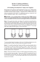
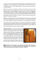
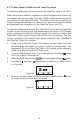
Step 6. After installing the ABS Power Splice harness, connect the 3-pin
power connector, (P3 in Figure 16) to the SmarTire Trailer-Link
™
TPMS Wiring
Harness, (P3 in Figure 17). Then route the harness along the underside of the
trailer, taking care to avoid any slider mounts and suspension components.
Secure the harness every foot with zip ties. Connect the other end of the
harness, P1 in Figure 17 to the SmarTire Trailer-Link ECU.
C
C
Detail C-C
P4
P1
P2
A
A
Detail A-A
P5
P4
P3
B
B
P3
Detail B-B
P1
DTM06-3S-E007
DEUTSCH
1
2
3
4
5
6
12
11
10
9
8
7
DTM06-12SA-E007
Bullet Connector
B
A
Delphi Fuse
14
32
DTM06-4S-E007
64 Inch
12 Inch
8 Inch
36 Inch
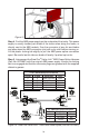
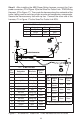
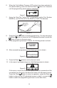
Figure 17 - 6 ft SmarTire
®
Trailer-Link
™
TPMS Harness Part No: K075868
P4 - Serial Port with LED Diagnostic
P4
PIN#
Designa-
tion
Color
Optional
Color
2
RS232-
Transmit
Blue Black
3
RS232-
Receive
White White
1 Ground Black* Yellow
4
LED-
Diagn.
Brown Brown
*
Splice Required into main GND wire
P1 - DTM06-12SA-E007
P1 -
Pin #
Designation Wire Color
Optional
Color
1 RS232-Transmit Blue Black
2 Not Used Sealing Plug ---
3 Brake Light Power Orange White
4 Not Used Sealing Plug ---
5 Not Used Sealing Plug ---
6 Ignition Power Red Red
7 Not Used Sealing Plug ---
8 LED - Diagnostic Brown Brown
9 Not Used Sealing Plug ---
10 Lamp Driver Purple Purple
11 Ground Black Yellow
12 RS232-Receive White White
P3 - ABS Power Splice Interconnection
P3 PIN# Designation Color Optional Color
2 Brake Light Power White White
1 Ground Black Yellow
3 Ignition Power Red Red