
User's Manual

Take Action Recommended in Step 3
Action
Code
Troubleshooting Checks To Make First
Then Do This
c Check the modulator wiring and also look for corrosion of its connector pins
c At the modulator harness, no continuity should be measured from any modulator pin to ground.
c Vbat is not measured from any modulator connector pin
c Verify proper modulator-valve activation (during the system start-up Chuff Test) with brake pressure
applied at power-up and/or using diagnostic tool. The wiring to the modulator may be reversed
c Refer to Action A and check for proper function and conguration of the WSS
• Clear the Blink
Codes (BCs)
• Is the same BC
back?
c Yes – see the
Service Data sheet
Troubleshooting
section and/or
contact the Bendix
Tech Team
c No – follow the
actions above for
any other remaining
BCs
c For a code of 11-1, check for damaged or corroded connectors and wiring. Clear DTCs if no problems
are found. If a DTC returns upon ignition ON, replace the module. Go to Step 4.
c For a code of 11-2, verify correct ABS conguration using blink codes or other diagnostic tool(s).
c If needed, reset the default ABS conguration and power-up to initiate auto-conguration. See Action E.
c Check for corroded/damaged wiring or connectors between the ECU
and J1587 Diagnostic
c Verify the following at the 18-pin ECU harness connector:
• +12V is not measured at the J1587 Diagnostic pins
• No continuity of the J1587 diagnostic pins to ground
• No continuity of the J1587 diagnostic pins to any other ECU pin(s)
c Verify the following at the J1587 4-pin Diagnostic connector:
• +12V is not measured at J1587 Diagnostic pins.
• No continuity of the J1587 diagnostic pins to ground
• No continuity of the J1587 diagnostic pins to any other ECU pin(s)
• Replace/repair J1587 Diagnostic wiring or components as required
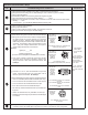
6
12
18
Looking into Premium TABS-6
Module Wire Harness, ECU
Connector Measure:
Pin 6 (Ignition Power),
Pin 18 (ground) and Pin 12
(Brake Light Power) to
Pin 1 (J1587+) and
Pin 7 (J1587-)
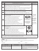
c Check for corroded/damaged wiring or connectors between the ECU and the
ABS indicator lamp.
At the ECU harness connector [Pin D of the 5-pin, or Pin 5 of the 18-pin], verify
the following:
• Continuity of the ABS indicator lamp wiring to the lamp (auxiliary device)
• +12V is not measured at ABS indicator lamp lead
Verify the following at the ABS indicator lamp lead:
• No continuity of the ABS indicator lamp lead to ground
• No continuity from the ABS indicator lamp lead to any other ECU pin(s)
• Replace/repair the ABS indicator lamp wiring or components as required
Reference Documents - Bendix
®
Service Data sheets:
SD-13-4767 (Bendix
®
TABS-6
™
Trailer ABS Module standard & premium controllers.)
Visit www.bendix.com for free downloads of Service Data Sheets, Warranty Policies, or to download/order copies of the SD sheets
Replace the ECU. If it is still under warranty coverage, le a claim and include:
a) the returned part; b) a copy of this document; and c) a print-out of the Bendix
®
ACom
®
Diagnostics report.
VIN #: _____________________________________________________ Claim #: ___________________
Vehicle Make: ________________________________________ Model: _______________ Mileage: _______________
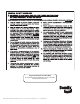
To Reset the DTCs Using
a Bendix
®
TRDU
™
To Reset the DTCs Using Bendix
®
ACom
®
Diagnostics
Alternate Method to Reset the DTCs
• Reset Diagnostic Trouble Codes by
holding a magnet over the reset of the
Bendix
®
Trailer Remote Diagnostic Unit
(TRDU
™
) tool for less than 6 seconds.
• Use the Reset Diagnostic Codes feature.
• Depress and release the stop lamp switch (or brake pedal) ve (5)
times within 15 seconds of switching the ignition ON to reset the
diagnostic trouble codes. There will be a BC of 1-1 will be displayed
if all trouble codes were cleared but if any trouble codes remain the
ABS light will remain on.
Step 4
(If necessary)