
User's Manual
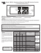

Take Action Recommended in Step 3
Action
Code
Troubleshooting Checks To Make First
Then Do This
c Verify that the number of WSSs found in Step 1 match the stored conguration
c Verify that the sensor wiring has no visible damage or has no shorts to ground or battery
c Verify proper tire ination
c Check that the WSS’s face is touching the exciter ring/tone ring face
c Verify 950-1950 ohms across sensor leads. Reading: .............. ohms*,
c While turning the wheel at 0.5 revs/sec, verify a minimum of 0.25 AC volts across the sensor leads.
Reading: ........ volts*
*
Out of range? – go to the Bendix BW2453 WSS inspection guide
• Clear the Blink
Codes (BCs)
• Is the same BC
back?
c Yes – see the
Service Data sheet
Troubleshooting
section and/or
contact the Bendix
Tech Team
c No – follow the
actions above for
any other remaining
BCs
c Verify correct tire size as desired
c Verify proper tire ination
c Verify correct number of exciter ring teeth, on both sides of the axle
c Verify that the ECU has the proper tire size settings
c Verif y that the wiring and connections are free from damage
c With ignition power to the trailer, measure voltage between
the Ignition Power pin and the Ground pin of the ECU
harness connector. Repeat voltage measurement with
Brake Lamp Power pin and Ground pin of the ECU harness
connector. The operating range of the module is 8.0-16.0
VDC. Verify that voltage measurements are equal to
vehicle voltage at both ends of the harness.
Readings:
Ignition pin
_____
Vdc
Brake Lamp Power pin
_____
Vdc
(Incorrect? Then investigate the harnesses and connectors)
c If the proper voltage is measured at the ECU harness
connector, and no corrosion or damage is found on the
wiring connectors or ECU, then replace the module. Go
to Step 4.
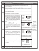
Looking into
the system’s
main ECU wire
harness 18-Pin
connector
(Bendix
®
TABS -6
Premium)
Pin 6 (Ignition Power), Pin 12 (Brake Lamp
Power), Pin 18 (Ground)
Looking into
the system’s
main ECU wire
harness 5-Pin
Connector
(TABS-6
Standard)
Pin B (Ignition Power)
Pin A (Brake Lamp Power) Pin E (Ground)
c If the BC is 7-1 or 7-2, clear the active BC and cycle the
power. Check the BC again, and if the same code is
returned, replace the module. Go to Step 4.
c Check the following pins if the system is equipped with more
than one modulator (Bendix TABS-6 Premium ECU only):
• 3.0 to 8.0 Ohms across the Hold/Common connector pins
• 3.0 to 8.0 Ohms across the Exhaust/Common pins
• 6.0 to 16.0 Ohms across the Hold/Exhaust pins
• No continuity should be measured from any modulator pin
to ground
• Vbat is not measured from any modulator connector pin
• Modulator/connector wiring and pins should not be damaged
or corroded
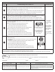
(Looking
into the wire
harness
connector)
18-Pin
Connector
(TABS-6
Premium)
Pin 3 is MOD2 Common, Pin 4 is MOD3
Common
Pin 9 is MOD2 exhaust, Pin 10 is MOD3
exhaust
Pin 15 is MOD2 Hold, Pin 16 is MOD3
Hold
Looking into
Modulator
Connector
Pins:
Pin 1 (Release), Pin 2 (Common)
Pin 3 (Hold)
c Verify the correct ABS conguration using blink codes or other diagnostic tool(s).
If needed, reset to the default ABS conguration and power-up to initiate an auto-conguration.