
User manual

Chapter 8 Sample PLC-5 Program
74
ADVANCED MICRO CONTROLS INC.
Thu Feb 22, 1996 Page 4
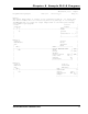
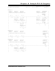
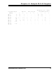
Program Listing Report PLC-5/11 File 2762_17 Rung 2:8
Rung 2:8
| set when |2762-17 BT|set to one shot 2762-17 |
| 2762-17 |module |program control Block |
| keyboard |status |resolver Transfer |
| in use |error |data Write |
| |exists | |
| N10:20 B3 I:011 B3 +BTW--------------------+ |
+----]/[----+---]/[----+---] [----++--[ONS]-----+BLOCK TRANSFER WRITE +-(EN)-+
| 12 | 0 | 00 || 1 |Rack 00| |
| | |set to || |Group 6+-(DN) |
| | |program || |Module 0| |
| | |position || |Control block BT9:1+-(ER) |
| | |data || |Data file N10:80| |
| | | I:011 || |Length 12| |
| | +---] [----+| |Continuous N| |
| | | 01 || +-----------------------+ |
| | |set to || |
| | |preset || |
| | |position || |
| | | I:011 || |
| | +---] [----+| |
| | 03 | |
| |set to | |
| |program | |
| |auxiliary | |
| |commands | |
| | I:011 | |
| +---] [----------------+ |
| 02 |
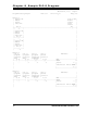
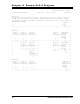
Rung 2:9
The following three rungs are used to determine the channel 1 output status of
an AMCI 2762-17 module from the Input Image Table motion status bits. These
three rungs should be used when the direction parameter is set to "P" or CW
increasing readings.
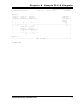
| comment |
| coil |
| N7:0 |
+----------------------------------------------------------------------( )-----+
| 1 |