
User manual


Chapter 8 Sample PLC-5 Program
ADVANCED MICRO CONTROLS INC.
71
Thu Feb 22, 1996 Page 1
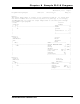
Program Listing Report PLC-5/11 File 2762_17 Rung 2:0
Rung 2:0
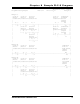
The output image table of a PLC-5 is not cleared at power up. To insure that
the 2762-17 module will not initiate any motion at power up, it is strongly
recommended that you clear the output image table on the first pass through
your ladder logic program.
| first 2762-17 |
| pass bit module |
| S:1 +MOV---------------+ |
+----] [--------------------------------------------------+MOVE +-+
| 15 |Source 0| |
| | | |
| |Destination O:007| |
| | 0| |
| +------------------+ |
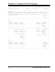
Rung 2:1
| 2762-17 2762-17 |
| BTR Enable Block |
| bit Transfer |
| Read |
| BT9:0 +BTR--------------------+ |
+----]/[----------------------------------------+BLOCK TRANSFER READ +-(EN)-+
| EN |Rack 00| |
| |Group 6+-(DN) |
| |Module 0| |
| |Control block BT9:0+-(ER) |
| |Data file N10:0| |
| |Length 12| |
| |Continuous N| |
| +-----------------------+ |
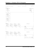
Rung 2:2
| 2762-17 2762-17 |
| BTR Done bufferred |
| bit BTR data |
| BT9:0 +COP--------------------+ |
+----] [---------------------------------------------+COPY FILE +-+
| DN |Source #N10:0| |
| |Destination #N10:20| |
| |Length 12| |
| +-----------------------+ |