
User manual


Chapter 1 Introduction to the 2762-17
ADVANCED MICRO CONTROLS INC.
7
AMCI Compatible Transducers
The 2762-17 is compatible with the following NEMA 4 transducers manufactured by
AMCI.
!
HTT-20-100: 100 turn absolute position transducer
!
HTT-20-180: 180 turn absolute position transducer
!
HTT-20-1000: 1,000 turn absolute position transducer
!
HTT-20-1800: 1,800 turn absolute position transducer
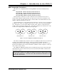
Each transducer contains two resolvers. The first resolver, called the fine resolver, is
attached with a flexible coupler directly to the shaft. The second resolver, called the coarse
resolver, is geared to the fine. This gear ratio, either 99:100 or 179:180 determines the total
number of turns the transducer can encode.
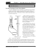
At the mechanical zero of the transducer the electrical zeros of the two resolvers are aligned.
See Figure 1.4A. After one complete rotation, the zero of the coarse resolver lags behind the
zero of the fine by one tooth, either 1/100 or 1/180 of a turn. After two rotations the lag is
2/100 or 2/180. See Figures 1.4B and 1.4C. After 100 or 180 turns, the electrical zeros of the
resolvers are realigned and the multiturn cycle begins again.
The 2762-17 simultaneously reads the resolvers every 800 µSec. The fine resolver yields the
absolute position within the turn directly. Using a proprietary algorithm, the 2762-17
determines the number of turns completed by the difference in positions of the two resolvers.
The absolute multiturn position is then calculated as ((number of turns completed * counts per
turn) + fine resolver position).
The 1,000 and 1,800 turn transducers have an additional 10:1 gear ratio between the input
shaft and the fine resolver. Therefore they can encode ten times the number of turns but at a
tenth of the resolution.
To the 2762-17 module, the 1,000 and 1,800 turn transducers appear to be 100
or 180 turn transducers. Therefore only 100 and 180 turn transducers are
discussed in this manual.
FINE
0
0
COURSE FINE
0
0
COURSE FINE
0
0
COURSE
A
Mechanical Zero
B
After One Turn
C
After Two Turns
Figure 1.4 Resolver Alignment in Multiturn Transducers