
User manual


Chapter 8 Sample PLC-5 Program
ADVANCED MICRO CONTROLS INC.
69
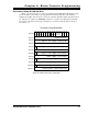
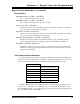
The following ladder logic program is an example of how block transfer
instructions can be used to interface the 2762-17 module to a PLC-5. The block
transfer functionality allows the PLC to read Status, Position, Velocity data as
well as parameter values from the 2762-17. It also allows the PLC to program
all setup information, as well as perform any error handling.
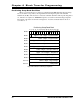
The program shows how to read and buffer the data from a 2762-17 module, and how a
single block transfer write instruction can be used to send the various setup and control
functions to the module. This program also shows how to restrict all block transfer write
programming when the module's keyboard is in use. It also restricts all programming but
auxiliary commands programming when there is a block transfer read module status error.
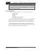
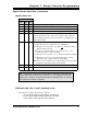
The 2762-17 module transmits the motor control output status, whether the outputs are on or
off, to the PLC in the block transfer read data. However, this may not be fast enough for some
applications. Rungs 2:9 through 2:12 can be used to determine the channel 1 output status from
the Motion Status Bits located in the input image table. These rungs should only be used when
the direction parameter is set to 'Positive' or CW increasing readings.