
User manual

Chapter 1 Introduction to the 2762-17
6
ADVANCED MICRO CONTROLS INC.
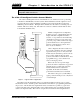
Brushless Resolver Description
The brushless resolver is unsurpassed by any other type of rotary position transducer in its
ability to withstand the harsh industrial environment. An analog sensor that is absolute over a
single turn, the resolver was originally developed for military applications and has benefited
from more than 50 years of continuous use and development.
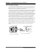
The resolver is essentially a rotary transformer with one important distinction. The energy
coupled through a rotary transformer is not affected by shaft position whereas the magnitude of
energy coupled through a resolver varies sinusoidally as the shaft rotates. A resolver has one
primary winding, the Reference Winding and two secondary windings, the SIN and COS
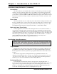
Windings. (See Figure 1.2, Resolver Cut Away View). The Reference Winding is located in
the rotor of the resolver, the SIN and COS Windings in the stator. The SIN and COS Windings
are mechanically displaced 90 degrees from each other. In a brushless resolver, energy is
supplied from the Reference Winding to the rotor by a rotary transformer. This eliminates
brushes and slip rings in the resolver and the reliability problems associated with them.
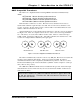
In general, the Reference Winding is excited by an AC voltage called the Reference Voltage
(V
R
). (See Figure 1.3, Resolver Schematic). The induced voltages in the SIN and COS
Windings are equal to the value of the Reference Voltage multiplied by the SIN or COS of the
angle of the input shaft from a fixed zero point. Thus, the resolver provides two voltages
whose ratio (SIN / COS = TAN , where = shaft angle) represents the absolute position of the
input shaft. Because the ratio of the SIN and COS voltages is considered, any changes in the
resolvers’ characteristics, such as those caused by aging or a change in temperature, are
ignored.
θ
R
R1 Red Wht
R2 l Wht
CO
Winding
4 lu
2 el
3 l
1 Red
IN
Winding
C
R
CO
θ
Rotary
Transformer
R
IN
θ
Wire Color
Fig 1.3 Resolver Schematic
SIN and COS W indings
Reference Winding
Fig 1.2 Resolver Cut away View