
User manual

Chapter 6 Block Transfer Programming
ADVANCED MICRO CONTROLS INC.
53
Transducer Setup Data (continued)
Programming Bit Values (continued)
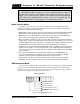
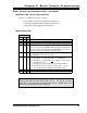
Decimal Point:
Bits five, four, and three define a binary number that sets the number of digits
to the right of the decimal point on the 2762-17 display. This parameter has
no affect on the data transmitted over the backplane.
Bit #
5 4 3
000
= 0 (xxxxxx)
001
= 1 (xxxxx.x)
010
= 2 (xxxx.xx)
011
= 3 (xxx.xxx)
100
= 4 (xx.xxxx)
101
= 5 (x.xxxxx)
1 1 0 Undefined
1 1 1 Undefined
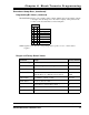
SGN:
Sign Bit: Set to 0 if the corresponding value is positive or set to 1 if the value is
negative.
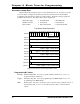
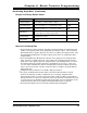
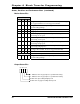
Ranges and Factory Default Values
Parameter Range Factory Default
Transducer Type
HTT-20-180, HTT-20-100 HTT-20-180
Count Direction
CW increasing, CCW increasing. CW increasing
Decimal Point
0 to 5 inclusive 0
Number of Turns
HTT-20-180: 0.1 to 180.0, 0.1 turn resolution
HTT-20-100: 0.1 to 100.0, 0.1 turn resolution 180.0
Scale Factor
2 to (Number of Turns * 4,096) 737,280
Linear Offset
-99,999 to (999,999 - FSC
†
)0
Preset Value
Linear Offset to (Linear Offset + FSC
†
)0
Upper Travel Limit
(Lower Travel Limit + 1) to (Linear Offset + FSC
†
) 737,279
Lower Travel Limit
Linear Offset to (Upper Travel Limit - 1) 0
† FSC: Full Scale Count = (Transducer Type {100 or 180} * (Scale Factor/Number of Turns)) - 1