
User manual

Chapter 6 Block Transfer Programming
52
ADVANCED MICRO CONTROLS INC.
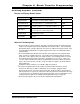
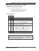
Transducer Setup Data
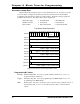
When the Transducer Setup bit, (bit 8) of the Command word is set, the 2762-17 uses the
rest of the data to configure the transducer specified by the LSB of the Command Word.
Configuring both transducers requires two block transfers. Transducer Setup programs the
parameters shown below. The data format is shown in figure 6.2.
!
Transducer Type
!
Count Direction
!
Decimal Point
!
Number of Turns
!
Scale Factor
!
Linear Offset
!
Preset Value
!
Upper Travel Limit
!
Lower Travel Limit
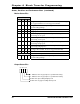
Fig 6.2 Transducer Setup Command Data Format
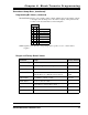
Programming Bit Values
ChNum:
Channel Number Bit. Set to 0 to program transducer channel one or set to 1 to
program transducer channel two.
TType:
Transducer Type Bit. Set to 0 if programming for an HTT-20-100 or set to 1 if
programming for an HTT-20-180.
DIR:
Direction Bit: Set to 0 if you want the count to increase with a clockwise rotation of
the transducer shaft or set to 1 if you want an increase with a counter-clockwise
rotation.
15 14 13 12 10 09 08 07 06 05 04 03 02 01 0011
Transducer Setup Command
0000 000100
ChNm
TType
Decimal
Point
DIR
Lower 3 digits: Scale Factor
Word 1
Upper 1, 2 or 3 digits: Scale Factor
Number of Turns
Word 0
Lower 3 digits: Linear Offset
Upper 1, 2 or 3 digits: Linear Offset
SGN
Word 2
Word 3
Word 4
Word 5
Word 6
Word 7
Word 8
Word 9
Word 10
Word 11
Lower 3 digits: Preset Value
Upper 1, 2 or 3 digits: Preset Value
SGN
Lower 3 digits: Upper Travel Limit
Upper 1, 2 or 3 digits: Upper Travel Limit
SGN
Upper 1, 2 or 3 digits: Lower Travel Limit
SGN
Lower 3 digits: Lower Travel Limit