
User manual

Chapter 5 PLC-5 BT Instructions
ADVANCED MICRO CONTROLS INC.
49
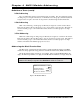
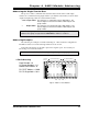
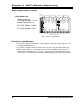
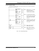
Programming Example
The following example assumes 1-Slot addressing and the 2762-17 module is I/O Rack 2,
I/O Groups 4 & 5 of the system.
Rung 1: BTR Instruction to the AMCI
module. Data will be
transferred every scan with
continuous transfer enabled.
Rung 2: Copy File Instruction buffers
the data from the module. This
insures that the program will
use the same data throughout
each scan.
Rung 3: The BT write is enabled when-
ever CR1 is latched on. Note
that the continuous parameter
is set to NO.
Rung 4: CR1 is latched on when a
BTW request is made.
Rung 5: CR1 is unlatched when the
BTW request is removed and
the BTW Done bit is set.
BLOCK XFER READ
RACK 2
GROUP 4
MODULE 0
CONTROL N7:20
DATA N7:25
LENGTH 12
CONTINUOUS
Y
(L)
(U)
BTW Request CR1
CR1
BTW Request
BTW
DN
(
EN
)
(
DN
)
COP
COPY FILE
SOURCE #N7:25
DEST #N7:40
LENGTH 12
(
ER
)
CR1
BLOCK XFER WRITE
RACK 2
GROUP 12
MODULE 0
CONTROL N14:0
DATA N14:5
LENGTH 12
CONTINUOUS
N
(
EN
)
(
DN
)
(
ER
)
Fig 5.1 PLC-5 Programming Example