
User manual

Chapter 5 PLC-5 BT Instructions
ADVANCED MICRO CONTROLS INC.
47
Overview
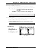
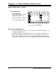
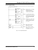
All PLC-5 processors have Block Transfer Instructions in their instruction sets. There are
five parts to PLC-5 BT Instructions. They are:
!
Module Address
- The I/O Rack, Group, and Slot Numbers where the module is located.
!
Control Block
- The starting address of the five word block in memory that controls the
Block Transfer.
!
Data File
- The starting file address that stores the data written to or read from the module.
!
File Length
- The number of words needed to store the data written to or read from the
module.
!
Continuous Parameter
- Determines how often the block transfer is carried out.
Module Address
The Module address is the I/O rack, group, and slot numbers where the module is located in
the system. The I/O rack, group, and slot numbers are entered separately in the block transfer
instruction.
Control Block
The Control Block is a block of five words that control the actual transfer of data. The
address entered into the BT instruction is the first address of the block. The control block must
have an integer or BT data type and can be its own file or part of a larger file.
Each BT Instruction requires a separate control block. This is true even if a BTW
and BTR access the same module.
Data File
The Data File is the block of words that stores the information read from or written to the
2762-17. The Data Address is the first address of the file. The data file must have an integer or
binary data type and can be a separate file or part of a larger file.
File Length
The File Length is the number of words in your data file. When programming a BTR
instruction, you can set the Block Length to 00. This will reserve 64 words in the PLC-5
memory, but the module will only transmit the number of words necessary. When
programming a BTW instruction, the number of words must equal twelve.
The File Length of a BTW instruction
MUST
equal 12. Using a File Length of
zero will cause a Program Command Error.