
User manual

Chapter 4 AMCI Module Addressing
ADVANCED MICRO CONTROLS INC.
45
Addressing the Single Transfer Data
The processor writes commands and reads status data from the 2762-17 with single
transfers. To communicate using single transfers you must know the memory locations in the
output and input image tables associated with the module.
!
PLC-5 Input Table:
The characters "I:" followed by a three digit number. The
first two digits are the I/O rack number, followed by the I/O
group number.
!
Output Table:
The characters "O:" followed by a three digit number. The
first two digits are the I/O rack number, followed by the I/O
group number.
Note: The I/O group number used for single transfers is always the lowest, odd
numbered I/O group assigned to the
Slot Pair
the 2762-17 resides in.
Addressing Examples
The following are examples of module addressing for 1-Slot and ½-Slot configurations.
The PLC-5 addresses for block and single transfers are also shown.
In the following figures, the module is placed in a single slot pair. See Installing the
Module Pg. 37 for more information.
The 2762-17 must be installed in a single slot pair to operate properly.
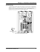
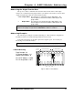
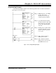
1-Slot Addressing
Rack Number: 01
I/O Group Numbers: 0,1
Module Slot Number: 0
PLC-5 BT Address = 0100
PLC-5 Single Addr = I:011
0 0 0 0 0 0 0 0
I/O Group
Number
Module Slot Numbers
0 0 0 0 0 0 0 0
0 1 2 3 4 5 6 7 0 1 2 3 4 5 6 7
I/O Rack Num ber 0 I/O Rack Number 1
Fig 4.2 2762-17 1-Slot Address