
User manual

Chapter 4 AMCI Module Addressing
44
ADVANCED MICRO CONTROLS INC.
Definition of Terms (cont'd)
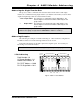
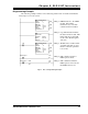
2-Slot Addressing
Two slot addressing cannot be used with the 2762-17 module. Two slot addressing assigns
one I/O group to a slot pair in the chassis. A minimum of two I/O groups (32 I/O bits) must be
assigned to the slot pair so the 2762-17 can perform concurrent single and block transfers.
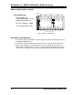
1-Slot Addressing
With 1-slot addressing, one I/O group (16 I/O bits) is assigned to each slot in the chassis.
Therefore the 2762-17 has two I/O groups to use, one in each slot of its slot pair. The 2762-17
uses the first I/O group to control its block transfers and the second I/O group for its single
transfers.
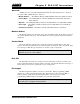
½-Slot Addressing
With ½-slot addressing, two I/O groups (32 I/O bits) are assigned to each slot in the chassis.
Therefore the 2762-17 has four I/O groups to use, two in each slot of its slot pair. The 2762-17
uses the first I/O group to control its block transfers and the second I/O group for its single
transfers. The third and fourth I/O groups are not used.
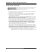
Addressing the Block Transfer Data
The PLC reads operating data from the 2762-17 module with block transfer read (BTR)
instructions and programs the setup parameters with block transfer write (BTW) instructions.
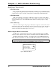
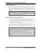
The block transfer address is made up of four digits. They are the I/O Rack Number (two
digits), the I/O Group Number (one digit), and the Module Slot Number (one digit, always 0).
Note: The I/O Group number used for block transfers is always the lowest, even
numbered I/O Group assigned to the
Slot Pair
the 2762-17 resides in.
MODULE ADDRESS = RGS
I/O Rack Number
I/O Group Number
Module Slot Number
Fig 4.1 BT Module Address