
User manual

Chapter 4 AMCI Module Addressing
ADVANCED MICRO CONTROLS INC.
43
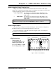
This chapter explains how to address a 2762-17 in a programmable controller system.
Remember that a 2762-17 performs concurrent block and single transfers.
When you configure your programmable controller system, you specify a unique address for each slot
of each chassis in the system. An I/O Rack number and an I/O Group Number make up each address. A
Module Slot number further specifies a block transfer address.
Note that an I/O Chassis is not the same as an I/O Rack. An I/O Chassis is the physical
enclosure that the processor and I/O modules plug into. An I/O Rack Number is part of a
modules' address in the system. Each I/O Chassis can have ¼ to 4 I/O Racks associated with it.
Definition of Terms
Block Transfer
The transfer of a block of data over the backplane in one scan. A Block Transfer Read
transmits data from an I/O module to the processor. A Block Transfer Write transmits data
from the processor to an I/O module. Up to sixty-four words can be transmitted per block
transfer. The 2762-17 requires block transfers of twelve words.
Single Transfer
The transfer of a single unit (8, 16, or 32 bits) of data over the backplane. The transfer
occurs between I/O Modules and the processors' Input or Output Image Tables. Single
transfers occur automatically every I/O scan and can occur during a program scan with the use
of Immediate Input and Immediate Output Instructions. In addition to using block transfers, the
2762-17 accepts and transmits single transfer data 16 bits at a time.
I/O Rack
The number of I/O Racks in the system, not the number of chassis, define the programm-
able controller system. In PLC-5 systems the first I/O Rack is assigned the number 0. Each
I/O Rack is further divided into 8 I/O Groups.
When specifying a block transfer or single transfer address all I/O Rack and
Group numbers are expressed in octal. (i.e. 00, 01, 02, ... 06, 07, 10, 11, ......)
I/O Group
An I/O Group consists of 16 input and 16 output bits. Eight I/O Groups, numbered 0
through 7, make up a single I/O Rack.
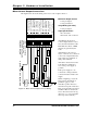
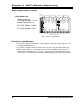
Slot Pair
Backplane slots of an I/O Chassis are numbered consecutively from zero starting at the
leftmost I/O slot. A slot pair is two adjacent backplane slots, the left of which is even
numbered. Most A-B chassis have the slots numbered on the backplane silk screen.
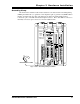
A 2762-17 module must be installed in a single slot pair to operate properly. See
Installing the Module
, Pg. 37. The figures in this chapter show the module in a Slot Pair.