
User manual

Chapter 3 Hardware Installation
42
ADVANCED MICRO CONTROLS INC.
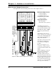
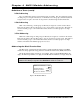
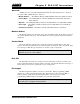
Motor Control Output Connections
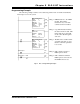
The figure below shows the wiring to the motor control output connector.
Maximum Output Current
2 Adc per Output
5 Adc per Channel
Surge Rating (10 mSec)
4 Adc per Output
Input Specifications
10 to 24 Vdc/ac
10 mA max. turn on current
All cabling from the motor
control outputs must be routed
away from the transducer cable.
This limits the effects of EMI
that may be generated by the
loads.
All inductive loads, (motors,
relays, solenoids, etc.) connected
to the control outputs must have
surge suppressors installed on
their power terminals.
All return connections from the
loads must be terminated as
close to the power supply as
possible.
If the power supply is to be
connected to earth ground, the
connection must be made at the
supply.
When configuring you system,
first set the Count Direction
parameter (page 8) so the
transducer position increases
when the load position increases.
Then reverse the Motor Forward
and Motor Reverse leads if the
motor drives the load in wrong
direction. (i.e. A Jog Up makes
the load position decrease.)
LOAD 1
LOAD 2
LOAD 3
LOAD 4
POWER
SUPPLY
12-40 Vdc
+
-
+
-
+
-
+
-
+
-
LOAD 5
LOAD 6
LOAD 7
LOAD 8
POWER
SUPPLY
12-40 Vdc
+
-
+
-
+
-
+
-
+
-
MOTOR CONTROL
OUTPUT CONNECTOR
AMCI Part #: MS-141
Weidmüller Part #: 128291
2762-17 Front Panel
+ External Jog Input
– External Jog Input
V
IN
1 / Fuse Indicator
CH 1 Motor Forward
CH 1 Motor Reverse
CH 1 High Speed
CH 1 Low Speed
V
IN
1 Common
V
IN
2 / Fuse Indicator
CH 2 Motor Forward
CH 2 Motor Reverse
CH 2 High Speed
CH 2 Low Speed
V
IN
2 Common
14
13
12
11
10
9
8
7
6
5
4
3
2
1
+
-
POWER
SUPPLY
10-24 Vac/dc
MOMENTARY OR SPST SWITCH
Figure 3.5 Motor Control Output Connector Wiring