
User manual

Chapter 3 Hardware Installation
ADVANCED MICRO CONTROLS INC.
37
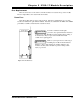
This chapter describes how to install the 2762-17 into the I/O chassis as well as
the HTT-20 transducers and cable. Suggested wiring of the motor control
outputs and external jog input is also included.
Power Requirements
The 2762-17 draws it power from the I/O chassis + 5Vdc supply. The maximum current
draw is 800 mA. Add this to the power requirements of all other modules in the chassis when
determining maximum system load to avoid exceeding backplane or power supply capacity.
Installing the Module
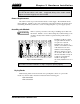
Remove system power before removing or installing any module in an
I/O chassis. Failure to observe this warning may result in damage to the
module's circuitry and/or undesired operation with possible injury to
personal.
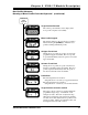
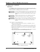
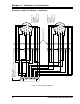
Install the module in a single
slot pair within the chassis. A
slot pair is two adjacent
backplane slots, the left of
which is even numbered. Most
A-B chassis have the slots
numbered on the backplane
silkscreen. Figure 3.1 shows
two modules. The module on
the left is installed correctly in
a single slot pair while the
module on the right is
incorrectly installed in two slot
pairs.
The 2762-17 must be installed in a single slot pair to operate properly.
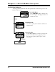
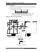
Keying Bands
Plastic keying bands can be inserted into the top backplane connector to prevent the
insertion of other modules. Insert the bands between the following pins:
!
Pins 28 and 30
!
Pins 32 and 34.
WARNING
!
Fig 3.1 Module Installation