
User manual

Chapter 2 2762-17 Module Description
36
ADVANCED MICRO CONTROLS INC.
Fuse Replacement (continued)
Output Fuses
If an Output Fuse fails, the module must be opened before the fuse can be replaced. The
factory installed fuses are 7A fast blow, Littelfuse Inc. part # 225007. A fuse kit of five fuses is
available from AMCI. The AMCI part number for the kit is SKF-4.
To insure continued and adequate protection, any replacement fuse must
have a rating of 7 Amp Fast Blow. Using a higher ampere rating or slow
blow fuses may not protect the module if the fault conditions are again
applied.
Output fuse replacement should be done in an ESD safe environment
because the module must be opened to replace the output fuses.
Remove system power before removing or installing any module in the
I/O Chassis. Failure to observe this warning can result in damage to the
module's circuitry and/or undesired operation with possible injury to
personal.
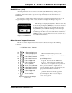
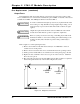
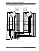
Refer to figure 2.11 when replacing the fuses.
1)
Remove the module from the I/O chassis and lay it on an ESD mat so that it is
orientated as it is in the picture.
2)
Remove the six screws that have boxes around them and arrows pointing to them.
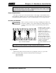
3)
Gently open the module like a book, with the bottom of the panel going to the left.
4)
Replace the fuse. Channel 1 fuse is closest to pin 14 of the connector. Channel 2
fuse is closest to pin 6.
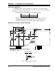
5)
Reposition the side panel onto the unit making sure the ribbon cable is not pinched
between the panel and the rest of the module. Replace the screws.
CAUTION
!
CAUTION
!
WARNING
!
CHANNEL 1
FUSE
CHANNEL 2
FUSE
Figure 2.11 Output Fuse Placement