
User manual

Chapter 2 2762-17 Module Description
34
ADVANCED MICRO CONTROLS INC.
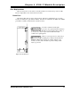
Transducer Input Connector
The transducer input connector has fourteen contacts and accepts the following connector
!
AMCI Part #: MS-14
!
Phoenix Part #: MSTB2.5/14-ST-5.08
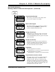
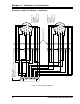
Figure 2.9 shows the pinout to industry standard resolver wire designations. A cable
diagram is given in chapter 3, Transducer Cable Installation, page 39. An engineering print is
given at the back of the manual. Print # B1091.
!
R1/R2 - Reference Winding
!
S1/S3 - COS winding
!
S2/S4 - SIN Winding
S4, CH2 Fine
S1, CH2 Fine
S4, CH2 Course
S3, CH2 Course
S2, S3, CH2 Fine and S1, S2 CH 2 Course
CH 2 Shields
S4, CH1 Fine
S1, CH1 Fine
S4, CH1 Course
S3, CH1 Course
S2, S3, CH1 Fine and S1, S2 CH 1 Course
CH 1 Shields
R2, CH 1 and CH2
R1, CH1 and CH2
14
13
12
11
10
9
8
7
6
5
4
3
2
1
Figure 2.9 Transducer Input Connector