
User manual

Chapter 2 2762-17 Module Description
26
ADVANCED MICRO CONTROLS INC.
Position Display
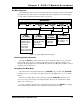
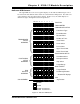
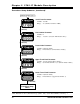
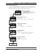
As shown in figure 2.5a, the Position Display shows the current position when a transducer
is properly attached to the channel. Figures 2.5b and 2.5c show the display when there is a
transducer fault. Figure 2.5b is the channel 1 display. Figure 2.5c is the channel 2 display.
There are four major causes of a transducer fault.
!
Broken or intermittent transducer cable
!
Non-compatible transducer
!
Improper wiring of the transducer Cable
!
Faulty Transducer.
PLC SERIES PLC SERIES PLC SERIES
Fig C
TRANSDUCER FAULT
CHANNEL 2
Fig B
TRANSDUCER FAULT
CHANNEL 1
Fig A
CURRENT POSITION
Figure 2.5 Position Displays
The red FAULT LED is lit when there is a transducer fault. If this LED is on while the
position is displayed, the fault is on the other channel. Use the [NEXT] key to switch to the
other channel. The fault can be cleared by pressing the [CLEAR] key if the 'Err1' message is
blinking.
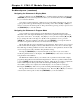
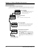
Tachometer Display
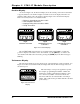
The tachometer display shows the current speed of the transducer in counts per minute. See
Figure 2.6. If there is a transducer fault, the display will show the 'Err1' messages instead of
the current speed.
The relationship to load speed is application specific.
For example, programming the Number of Turns and
Scale Factor parameter such that the transducer rotates
one count for every 0.001" of load travel means the
tachometer will read out in thousandths of an inch per
minute. This equals inches per minute with three decimal
point accuracy.
PLC SERIES
Figure 2.6 Tachometer
Display