
User manual

Chapter 2 2762-17 Module Description
ADVANCED MICRO CONTROLS INC.
25
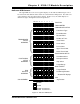
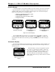
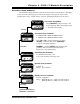
Indicator LED Patterns
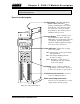
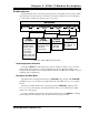
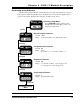
The eight LEDs above the seven segment displays are the indicator LEDs. Figure 2.4 is a
list of the menu and submenu items and the associated indicator LED pattern. Note that some
of the parameters have the same indicator pattern. In these cases, the actual displays are
different enough to distinguish between the parameters.
POS TAC SF O A B C D
POSITION
TACHOMETER
TRANSDUCER SETUP
Transducer Type
Count Direction
Decimal Point
Number of Turns
Scale Factor
Linear Offset
Preset Value
Upper Travel Limit
Lower Travel Limit
POSITIONING SETUP
OverShoot Offset
Low Speed Offset
Stop Offset
Target Range
RUN PROFILE
Target Position
Positioning Direction
All other RP Displays
JOG
Jog Position
TRANSDUCER
SETUP
SUBMENU
POSITIONING
SETUP
SUBMENU
RUN
PROFILE
SUBMENU
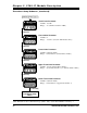
JOG SUBMENU
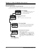
LED OFF
LED ON
LED OFF For Channel 1
LED ON For Channel 2
Figure 2.4 Indicator LED Patterns