
User manual

Chapter 2 2762-17 Module Description
22
ADVANCED MICRO CONTROLS INC.
Program Mode vs. Display Mode
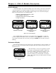
The 2762-17 front panel has two operating modes.
!
Program Mode - (Yellow PRG light on) T
he parameters can be modified from the
keyboard. Move profiles can be initiated and the position can be
jogged from the module.
!
Display Mode - (Yellow PRG light off)
The parameters can be viewed, but not
modified. Move profiles cannot be initiated but the position can
still be jogged.
Program Mode and Display Mode refer to the modules' front panel only. It does not refer to
the backplane interface. The 2762-17 is not programmable from the backplane only under two
conditions. First is when a parameter is being modified from the keyboard. Second is when a
move profile or jog is in process.
The 2762-17 can be locked in display mode in two ways. The first is by removing a jumper
on the module. The second is with a processor instruction. It is usually good practice to lock
the module in display mode once the system is operational. This will prevent someone from
accidentally changing the 2762-17's parameters while the system is running. The only times
that changes to the programming should be allowed are during set-up or trouble shooting
procedures.
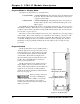
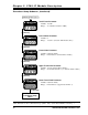
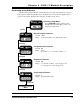
Program Switch
The Program Switch is used to quickly enable or
disable program mode as long as the 2762-17 is not
locked in display mode. The module is in program
mode when the switch is pushed towards the back
of the module. The module is in display mode
when the switch is pushed towards the front of the
module. The yellow PRG light is on when the
2762-17 is in program mode.
The Program Switch can be disabled by remov-
ing the jumper on the two pin header next to the
switch. Removing this jumper locks the 2762-17 in
display mode. You can also lock the module in
display mode with the Auxiliary Command Disable
Keyboard. See page 18.
Remove system power before
removing or installing any
module in an I/O chassis. Failure to observe this
warning can result in damage to the module's
circuitry and/or undesired operation with possible
injury to personnel.
Two Pin Header
with Jumper Installed.
Program Switch in
Program Mode position.
Figure 2.2 Program Switch
WARNING
!