
User manual

Chapter 2 2762-17 Module Description
ADVANCED MICRO CONTROLS INC.
21
This chapter describes the physical layout of the 2762-17 module as well as
keyboard programming.
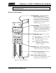
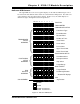
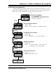
Front Panel Description
Program Switch
- (On other side of PC
Board, hidden from view.)
Used to
enable programming the 2762-17 from
the keyboard. A two pin header next to
the switch can be removed to disable
Program Mode. The switch can also be
disabled from the processor.
Function Display
-
Used to display position
data and parameter values. The eight
LED indicators designate what is showing
on the display. When programming a
parameter, a blinking digit in the display
shows the position of the
Cursor
.
Status Indicators
-
Indicates the operating
status of the module.
PRG -
Yellow light is on when the module is
in Program Mode.
RUN -
Green light is blinking when the
module is operating.
FAULT -
Red light is on when there is a
module fault. The type of fault is
shown on the display.
Keyboard
-
Used to examine or change the
programming of the module. Also used
to start a move profile or jog the position.
Transducer Input Connector
-
Connector
for the two AMCI transducers.
Motor Control Output Connector
-
Connector for the eight DC motor control
outputs and the external jog input.
Figure 2.1 2762-17 Front Panel