
User manual

Chapter 1 Introduction to the 2762-17
14
ADVANCED MICRO CONTROLS INC.
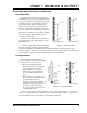
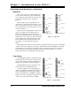
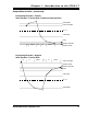
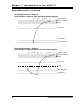
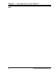
Sample Move Profiles
The following diagrams show the state of the motor control outputs based on
initial position and programmed parameters. The diagrams show the most
common positioning waveforms. All possible combinations are not shown.
Positioning Direction: Positive
Initial Position: Negative Side
OVERSHOOT
OS - LS
LOW SPEED
STOP
TARGET POSITION
TARGET RANGE
INITIAL POSITION
.200 in
HS
COAST COASTHSLS LS
Positioning Direction: Positive
Initial Position: Positive Side, Outside overshoot position
OVERSHOOT
LOW SPEED
STOP
TARGET POSITION
TARGET RANGE
INITIAL POSITION
.200 in
COASTHS LS