User Manual 2762-17 Intelligent Position Control Module Allen-Bradley 1771 I/O Module Manual: 940-57080
General Information Important User Information The products and application data described in this manual are useful in a wide variety of different applications. Therefore, the user and others responsible for applying these products described herein are responsible for determining the acceptability for each application. While efforts have been made to provide accurate information within this manual, AMCI assumes no responsibility for the application or the completeness of the information contained herein.
About This Manual Introduction This manual explains the operation, installation, programming, and servicing the 2762-17 Intelligent Position Control Module for the Allen-Bradley 1771 I/O programmable controller systems. It is strongly recommended that you read the following instructions. If there are any unanswered questions after reading this manual, call the factory. An applications engineer will be available to assist you. AMCI is a registered trademark of Advanced Micro Controls, Inc.
About This Manual Notes 4 ADVANCED MICRO CONTROLS INC.
Chapter 1 Introduction to the 2762-17 This chapter describes the uses and functionality of the 2762-17 module and compatible AMCI transducers. The 2762-17 Intelligent Position Control Module The 2762-17 Intelligent Position Control Module is a two channel, non-servo positioning controller for Allen-Bradley 1771 I/O systems. Each channel has four DC outputs for motor speed and direction control and utilizes a brushless resolver based transducer for absolute multiturn position feedback.
Chapter 1 Introduction to the 2762-17 Brushless Resolver Description The brushless resolver is unsurpassed by any other type of rotary position transducer in its ability to withstand the harsh industrial environment. An analog sensor that is absolute over a single turn, the resolver was originally developed for military applications and has benefited from more than 50 years of continuous use and development. The resolver is essentially a rotary transformer with one important distinction.
Chapter 1 Introduction to the 2762-17 AMCI Compatible Transducers The 2762-17 is compatible with the following NEMA 4 transducers manufactured by AMCI. ! HTT-20-100: 100 turn absolute position transducer ! HTT-20-180: 180 turn absolute position transducer ! HTT-20-1000: 1,000 turn absolute position transducer ! HTT-20-1800: 1,800 turn absolute position transducer Each transducer contains two resolvers. The first resolver, called the fine resolver, is attached with a flexible coupler directly to the shaft.
Chapter 1 Introduction to the 2762-17 2762-17 DC Outputs The 2762-17 has a total of eight DC motor control outputs, four per channel. Each channel has the following outputs. Motor Forward - Turns on to rotate the motor in one direction. Motor Reverse - Turns on to rotate the motor in the opposite direction of Motor Forward. ! High Speed - Turns on when motor can be driven at high speed. ! Low Speed - Turns on when the motor should be driven at low speed.
Chapter 1 Introduction to the 2762-17 Transducer Setup Parameters (continued) Number of Turns Use this parameter, along with the Scale Factor parameter, to set the correlation between the transducer position and the load position. This parameter is usually set to the number of rotations the transducer makes for the expected linear travel of the load. Its minimum value is 0.1 turns. Its maximum value is equal to the number of turns of the transducer, 100 or 180 turns, with 0.1 turn resolution.
Chapter 1 Introduction to the 2762-17 Transducer Setup Parameters (continued) Linear Offset The Linear Offset is a fixed number that is added to the transducer position data. It adjusts the range of position values the 2762-17 uses. For example, a twenty inch expected travel is over a range of 35.000 to 55.000 inches. Programming a linear offset of 35,000 will force the position data to read from 35,000 to 55,000. The module can output positions between -99,999 and 999,999.
Chapter 1 Introduction to the 2762-17 Positioning Setup Parameters (continued) Overshoot Offset The Overshoot Offset can be programmed to any value between (Low Speed Offset +1) and Full Scale Count. Overshoot Offset Target Overshoot 1.599 in Overshoot Offset The 2762-17 uses the Overshoot Offset to determine how far away from the Target Position to drive the load before beginning the approach to the Target Position.
Chapter 1 Introduction to the 2762-17 Positioning Setup Parameters (continued) Stop Offset Once on the correct side of the Target Position, the Stop Offset defines the position at which the motor outputs are turned off at the end of the move profile. The load then coasts to the Target Position. The Stop Offset can be programmed to any value between one and (Low Speed Offset - 1). If the Low Speed Offset equals zero, the Stop Offset can be programmed to any value between one and (Overshoot Offset -1).
Chapter 1 Introduction to the 2762-17 Positioning Setup Parameters (continued) Retry Value The Retry Value is only used when a move profile is initiated from the backplane and specifies the maximum number of attempts the 2762-17 will make to reach the target position if the first attempt failed. The Retry Value can be programmed to any value between 1 and 255. The default value is three. If you program a value greater than 255 or a value of zero, the module responds with and error message.
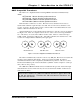
Chapter 1 Introduction to the 2762-17 Sample Move Profiles The following diagrams show the state of the motor control outputs based on initial position and programmed parameters. The diagrams show the most common positioning waveforms. All possible combinations are not shown. Positioning Direction: Positive Initial Position: Negative Side OVERSHOOT OS - LS LOW SPEED STOP TARGET POSITION .
Chapter 1 Introduction to the 2762-17 Sample Move Profiles (continued) Positioning Direction: Positive Initial Position: Positive Side, Inside overshoot position OVERSHOOT INITIAL POSITION OS - LS LOW SPEED STOP TARGET POSITION LS COAST HS LS COAST .200 in TARGET RANGE Positioning Direction: Negative Initial Position: Positive Side HS LS COAST HS LS COAST INITIAL POSITION .200 in TARGET RANGE TARGET POSITION STOP LOW SPEED OS - LS OVERSHOOT ADVANCED MICRO CONTROLS INC.
Chapter 1 Introduction to the 2762-17 Sample Move Profiles (continued) Positioning Direction: Negative Initial Position: Negative Side, Outside overshoot position HS LS COAST .200 in TARGET RANGE TARGET POSITION STOP LOW SPEED OVERSHOOT INITIAL POSITION Positioning Direction: Negative Initial Position: Negative Side, Inside overshoot position LS COAST HS LS COAST .200 in TARGET RANGE TARGET POSITION STOP LOW SPEED OS-LS INITIAL POSITION OVERSHOOT 16 ADVANCED MICRO CONTROLS INC.
Chapter 1 Introduction to the 2762-17 Sample Move Profiles (continued) INITIAL POSITION TARGET RANGE TARGET POSITION STOP LOW SPEED OS - LS OVERSHOOT Positioning Direction: Positive Initial Position: Negative Side This waveform shows the 2762-17 making four attempts to reach the Target Position by adjusting the Stop Offset. The 2762-17 will run the profile a maximum of four times before issuing an error message when the profile is initiated from the keyboard.
Chapter 1 Introduction to the 2762-17 Jogging the Load Position The 2762-17 allows you to manually jog the load position in one of three ways. From the processor, the modules' keypad, or an external input. The motor runs at low speed when jogging the position. ! C A U T IO N It is possible to jog the load past the upper or lower travel limits. Jogging from the Processor You jog the position from the processor by setting a bit in the output image table.
Chapter 1 Introduction to the 2762-17 Auxiliary Commands Auxiliary Commands are commands issued from the processor with a block transfer write. They affect the operation of the module. There are six commands: ! ! ! ! ! ! Clear Errors - Clears all transducer faults and programming errors. Disable Keyboard - Disables all programming from the keyboard. Move profiles cannot be initiated. Parameters can be monitored from the keyboard but they cannot be modified. Jogging from the keyboard is still enabled.
Chapter 1 Introduction to the 2762-17 Notes 20 ADVANCED MICRO CONTROLS INC.
Chapter 2 2762-17 Module Description This chapter describes the physical layout of the 2762-17 module as well as keyboard programming. Front Panel Description Program Switch - (On other side of PC Board, hidden from view.) Used to enable programming the 2762-17 from the keyboard. A two pin header next to the switch can be removed to disable Program Mode. The switch can also be disabled from the processor. Function Display - Used to display position data and parameter values.
Chapter 2 2762-17 Module Description Program Mode vs. Display Mode The 2762-17 front panel has two operating modes. Program Mode - (Yellow PRG light on) The parameters can be modified from the keyboard. Move profiles can be initiated and the position can be jogged from the module. ! Display Mode - (Yellow PRG light off) The parameters can be viewed, but not modified. Move profiles cannot be initiated but the position can still be jogged. Program Mode and Display Mode refer to the modules' front panel only.
Chapter 2 2762-17 Module Description The Menu System Programming the 2762-17 from the front panel involves navigating a menu system in which the parameters are broken down into sub-menus. The menu system layout is shown in Figure 2.3. The 2762-17 displays the current position on power up.
Chapter 2 2762-17 Module Description The Menu System (continued) Navigating the Submenus in Display Mode Once in a submenu, use the [FUNCTION] key to scroll through the parameters. Pressing the [FUNCTION] key when at the last parameter returns you to the main menu. Press the [ENTER] key to re-enter the submenu. You cannot program parameters or initiate a move profile while in display mode. You can jog the position. The jog submenu displays the current position.
Chapter 2 2762-17 Module Description Indicator LED Patterns The eight LEDs above the seven segment displays are the indicator LEDs. Figure 2.4 is a list of the menu and submenu items and the associated indicator LED pattern. Note that some of the parameters have the same indicator pattern. In these cases, the actual displays are different enough to distinguish between the parameters.
Chapter 2 2762-17 Module Description Position Display As shown in figure 2.5a, the Position Display shows the current position when a transducer is properly attached to the channel. Figures 2.5b and 2.5c show the display when there is a transducer fault. Figure 2.5b is the channel 1 display. Figure 2.5c is the channel 2 display. There are four major causes of a transducer fault.
Chapter 2 2762-17 Module Description Transducer Setup Submenu The Transducer Setup submenu contains all of the transducer setup parameters. The figure below and on the following page show all of the displays as they appear on the module. Default values, range of values and any special programming instructions are also listed. Transducer Setup Menu PLC SERIES Press [FUNCTION] or [å] to advance to the Positioning Setup Menu. Press [ä] to return to the Tachometer Display.
Chapter 2 2762-17 Module Description Transducer Setup Submenu (continued) Continued from Pg 2-7 Scale Factor Parameter PLC SERIES Default: 737,280 Range: 2 to (Number of Turns * 4096) [FUNCTION] Linear Offset Parameter PLC SERIES Default: 0 Range: -99,999 to (999,999 - Full Scale Count†) [FUNCTION] Preset Value Parameter PLC SERIES Default: 0 (Linear Offset) Range: Linear Offset to (Linear Offset + FSC†) [FUNCTION] Upper Travel Limit Parameter PLC SERIES Default: 737,279 (Linear Offset + FSC†) Range:
Chapter 2 2762-17 Module Description Positioning Setup Submenu The Positioning Setup submenu contains all of the positioning setup parameters except for Target Position and Positioning Direction. The figure below show all of the displays as they appear on the module. Default values and range of values are also listed. PLC SERIES Positioning Setup Menu Press [FUNCTION] or [å] to advance to the Run Profile menu. Press [ä] to return to the Transducer Setup menu.
Chapter 2 2762-17 Module Description Run Profile Submenu, Running a Move Profile From the Keyboard As the name implies, you initiate a move profile from this submenu. Move profiles cannot be initiated while in display mode. You must be in program mode to initiate a move profile. PLC SERIES Run Profile Menu Press [FUNCTION] or [å] to advance to the Jog menu. Press [ä] to return to the Positioning Setup menu.
Chapter 2 2762-17 Module Description Run Profile Submenu, Running a Move Profile From the Keyboard (continued) Continued from Pg 2-10 Target Position Reached PLC SERIES The current position flashes on the display if the move profile completes successfully. Move Profile Stopped PLC SERIES The display changes to 'Stop' if the move profile is halted. Pressing the [CLEAR] key while the move profile is running will halt the profile.
Chapter 2 2762-17 Module Description Jog Position Submenu The Jog position submenu has only one display that shows the current position or the transducer fault message. Run Profile Menu PLC SERIES Press [FUNCTION] or [å] to advance to the Position Display. Press [ä] to return to the Run Profile menu. [ENTER] Transducer Fault PLC SERIES You cannot jog the position while the channel is in transducer fault. Current Position PLC SERIES Use the [s] and [t] keys to increase or decrease the position.
Chapter 2 2762-17 Module Description NvRAM Error (Err2) All of the parameters are stored in a non-volatile static RAM memory when power is removed from the 2762-17. The NvRAM has an integral lithium battery that will maintain the parameter values in the absence of power for approximately ten years from the date of manufacture. It is remotely possible that the values can become corrupted through electrical noise or an inopportune power outage. If this occurs, the 2762-17 display will change to figure 2.7.
Chapter 2 2762-17 Module Description Transducer Input Connector The transducer input connector has fourteen contacts and accepts the following connector ! ! AMCI Part #: MS-14 Phoenix Part #: MSTB2.5/14-ST-5.08 Figure 2.9 shows the pinout to industry standard resolver wire designations. A cable diagram is given in chapter 3, Transducer Cable Installation, page 39. An engineering print is given at the back of the manual. Print # B1091.
Chapter 2 2762-17 Module Description Fuse Replacement There are three fuses on the 2762-17. The Power Fuse is located at the top of the module. The two Output Fuses are located inside the module. Power Fuse If the Power Fuse fails, it can be easily replaced. The factory installed fuse is a 3.5 Amp fast blow, Littelfuse Inc. part number 22503.5. Fuse kits are available from AMCI. The AMCI part number is SKF-3. Each fuse kit contains five fuses. Power Fuse 3.
Chapter 2 2762-17 Module Description Fuse Replacement (continued) Output Fuses If an Output Fuse fails, the module must be opened before the fuse can be replaced. The factory installed fuses are 7A fast blow, Littelfuse Inc. part # 225007. A fuse kit of five fuses is available from AMCI. The AMCI part number for the kit is SKF-4. ! C A U T IO N To insure continued and adequate protection, any replacement fuse must have a rating of 7 Amp Fast Blow.
Chapter 3 Hardware Installation This chapter describes how to install the 2762-17 into the I/O chassis as well as the HTT-20 transducers and cable. Suggested wiring of the motor control outputs and external jog input is also included. Power Requirements The 2762-17 draws it power from the I/O chassis + 5Vdc supply. The maximum current draw is 800 mA.
Chapter 3 Hardware Installation Transducer Mounting All AMCI HTT-20 resolver based transducers are designed to operate in the industrial environment and therefore require little attention. However, there are some general guidelines that should be observed to ensure long life. ! ! Limit transducer shaft loading to the following maximums: Radial Loads Axial Loads 100 lbs. (445 N) 50 lbs. (222.5 N) Minimize shaft misalignment when direct coupling shafts.
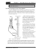
Chapter 3 Hardware Installation Transducer Cable Installation The transducer cable used with the 2762-17 module must be BELDEN 9731 or an exact equivalent. Complete cables can be ordered from AMCI with the part number C2TT-(x) where (x) is the length in feet. A wiring diagram of the C2TT-(x) cable is on the next page, figure 3.4. If you plan to make your own cables, the required cable and connectors can be ordered from AMCI.
14 13 12 11 10 9 8 7 6 5 4 3 2 1 RED BLK BRN BLK YEL BLK SHIELDS BLU BLK WHT BLK GRN BLK BLK RED BRN BLK YEL BLK SHIELDS BLU BLK WHT BLK Mates with all AMCI Two Channel Multi-turn Resolver Interface Modules GRN AMCI Part #: MS-14 Phoenix #: MSTB 1.5/14-ST-5.08 BLK Module Connector I J N H I G J N F BELDEN 9731 Cable.
Chapter 3 Hardware Installation Grounding Clamp The shield of the transducer cable must be attached to the chassis with a Grounding Clamp (AMCI part number GC-1) to guarantee a low impedance path to ground for any EMI radiation that may be induced into the cable. The drain wire from the Grounding Clamp must be connected to pin 3 of the MS-14 Transducer Input Connector. Pin 9 of the MS-14 connector is internally connected to pin 3 and does not need an additional wire.
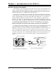
Chapter 3 Hardware Installation Motor Control Output Connections 2762-17 Front Panel Maximum Output Current 2 Adc per Output 5 Adc per Channel Surge Rating (10 mSec) 4 Adc per Output Input Specifications 10 to 24 Vdc/ac 10 mA max. turn on current LOAD 8 + LOAD 7 + LOAD 6 + - LOAD 5 + + - Figure 3.5 Motor Control Output Connector Wiring 42 All cabling from the motor control outputs must be routed away from the transducer cable. This limits the effects of EMI that may be generated by the loads.
Chapter 4 AMCI Module Addressing This chapter explains how to address a 2762-17 in a programmable controller system. Remember that a 2762-17 performs concurrent block and single transfers. When you configure your programmable controller system, you specify a unique address for each slot of each chassis in the system. An I/O Rack number and an I/O Group Number make up each address. A Module Slot number further specifies a block transfer address. Note that an I/O Chassis is not the same as an I/O Rack.
Chapter 4 AMCI Module Addressing Definition of Terms (cont'd) 2-Slot Addressing Two slot addressing cannot be used with the 2762-17 module. Two slot addressing assigns one I/O group to a slot pair in the chassis. A minimum of two I/O groups (32 I/O bits) must be assigned to the slot pair so the 2762-17 can perform concurrent single and block transfers. 1-Slot Addressing With 1-slot addressing, one I/O group (16 I/O bits) is assigned to each slot in the chassis.
Chapter 4 AMCI Module Addressing Addressing the Single Transfer Data The processor writes commands and reads status data from the 2762-17 with single transfers. To communicate using single transfers you must know the memory locations in the output and input image tables associated with the module. ! ! PLC-5 Input Table: The characters "I:" followed by a three digit number. The first two digits are the I/O rack number, followed by the I/O group number.
Chapter 4 AMCI Module Addressing Addressing Examples (cont'd) ½-Slot Addressing Rack Number: 02 I/O Group Numbers: 0,1,2,3 Module Slot Number: 0 I/O G ro u p N u m be r I/O R a ck 0 0,1 2,3 I/O R ack 1 4,5 6,7 0,1 2,3 4,5 6,7 I/O R a ck 2 0,1 2,3 I/O R ack 3 4,5 6,7 0,1 2,3 4,5 6,7 PLC-5 BT Address = 0200 PLC-5 Single Addr = I:021 0 0 0 0 0 0 0 0 0 0 0 M odule S lot N um bers 0 0 0 0 0 Fig 4.3 2762-17 ½-Slot Address Restrictions and Warnings 1.
Chapter 5 PLC-5 BT Instructions Overview All PLC-5 processors have Block Transfer Instructions in their instruction sets. There are five parts to PLC-5 BT Instructions. They are: ! ! ! ! ! Module Address - The I/O Rack, Group, and Slot Numbers where the module is located. Control Block - The starting address of the five word block in memory that controls the Block Transfer. Data File - The starting file address that stores the data written to or read from the module.
Chapter 5 PLC-5 BT Instructions Continuous Parameter The Continuous parameter controls how often the block transfer instruction is executed. When the continuous parameter is set to "NO", the block transfer is executed only on a false to true transition on the rung. This means that a non-continuous block transfer can occur at most every other scan.
Chapter 5 PLC-5 BT Instructions Programming Example The following example assumes 1-Slot addressing and the 2762-17 module is I/O Rack 2, I/O Groups 4 & 5 of the system. BLOCK XFER READ RACK 2 GROUP 4 MODULE 0 CONTROL N7:20 DATA N7:25 LENGTH 12 CONTINUOUS Y (EN) (ER) (DN) Rung 2: Copy File Instruction buffers the data from the module. This insures that the program will use the same data throughout each scan.
Chapter 5 PLC-5 BT Instructions PLC-5 Restrictions and Warnings ! W A R N IN G The following restrictions must be followed when using the 276217 in a PLC-5 System. If these restrictions are not followed, unpredictable operation may occur. 1. The 2762-17 will not operate in a chassis configured for 2-Slot addressing. The chassis must be configured for 1-Slot or ½-Slot addressing. 2. The 2762-17 module must be installed in a single slot pair. (See chapter 3, Installing the Module, page 37.
Chapter 6 Block Transfer Programming This chapter describes the format of the data written to and read from the 276217 using BTW and BTR instructions. It assumes familiarity with the setup and operation of the 2762-17. Descriptions of the modules' parameters given in chapter 1 are not repeated here. However, the default, minimum and maximum values that can be programmed are listed. If you are not familiar with the operation of the 2762-17, review chapters 1 and 2 before proceeding.
Chapter 6 Block Transfer Programming Transducer Setup Data When the Transducer Setup bit, (bit 8) of the Command word is set, the 2762-17 uses the rest of the data to configure the transducer specified by the LSB of the Command Word. Configuring both transducers requires two block transfers. Transducer Setup programs the parameters shown below. The data format is shown in figure 6.2.
Chapter 6 Block Transfer Programming Transducer Setup Data (continued) Programming Bit Values (continued) Decimal Point: Bits five, four, and three define a binary number that sets the number of digits to the right of the decimal point on the 2762-17 display. This parameter has no affect on the data transmitted over the backplane. 5 0 0 0 0 1 1 1 1 Bit # 4 0 0 1 1 0 0 1 1 3 0 1 0 1 0 1 0 1 = 0 (xxxxxx) = 1 (xxxxx.x) = 2 (xxxx.xx) = 3 (xxx.xxx) = 4 (xx.xxxx) = 5 (x.
Chapter 6 Block Transfer Programming Positioning Setup Data When the Positioning Setup bit, (bit 9) of the Command word is set, the 2762-17 uses the rest of the data to configure the positioning data of the transducer specified by the LSB of the Command Word. Configuring both transducers requires two block transfer writes. Positioning Setup programs the parameters shown below. The data format is shown in figure 6.3.
Chapter 6 Block Transfer Programming Positioning Setup Data (continued) Ranges and Factory Default Values Parameter Range Factory Default Target Position Linear Offset to (Linear Offset + FSC† ) 0 Overshoot Offset (Low Speed Offset + 1) to Full Scale Count† 1,000 Low Speed Offset 0 and (Stop Offset + 1) to (Overshoot Offset - 1) 500 Stop Offset 1 to (Overshoot Offset - 1) if Low Speed = 0 1 to (Low Speed -1) if Low Speed ≠ 0 100 Target Range 0 to Full Scale Count† 0 Retry Value 1 to 255
Chapter 6 Block Transfer Programming Auxiliary Commands Data When the Auxiliary Commands bit, (bit 10) of the Command Word is set, the 2762-17 uses bits 0 through 6 of the Command Word as data. Auxiliary Commands include clearing errors, enabling or disabling keyboard programming and defining the data transmitted to the processor with block transfer reads. Format of the block transfer read data is defined starting on page 58. Words 1 through 11 are not used but must be transmitted.
Chapter 6 Block Transfer Programming Auxiliary Commands Data (continued) Notes on Auxiliary Commands Data ! ! Setting both the DisKB and EnKB will cause a command error. One, and only one of the RSP, RTS, and RPS bits must be set when transmitting this command. Setting more than one, or none, will cause a command error. Preset Position Data When the Preset Position bit, (bit 11) of the Command Word is set, the 2762-17 presets the position of one or both of the transducers.
Chapter 6 Block Transfer Programming Block Transfer Reads Use block transfer reads to transfer complete module status to the processor. The block transfer is always twelve words long. The block transfer data takes one of three forms. ! ! ! Status, Position and Tachometer data Transducer Setup data Positioning Setup data. On power up, the 2762-17 transmits status, position and tachometer data. Use the Auxiliary Commands command with the RTS or RPS bit set to read the other types of data.
Chapter 6 Block Transfer Programming Status, Position and Tachometer Data (continued) KBIN Status Bit: Bit 12, Keyboard In Use This bit is set under the following conditions. ! ! ! The keyboard is being used to program any parameter. A move profile initiated from the keyboard is in progress. The position is being jogged from the keyboard. Module Status Bits Bit # 10 09 08 0 0 0 0 0 1 0 1 0 0 1 1 1 0 0 1 0 1 1 1 1 1 0 1 No Errors. Module operating without errors. Transducer Fault.
Chapter 6 Block Transfer Programming Status, Position and Tachometer Data (continued) Motion Status Bits 07 Bit # 06 05 04 0 0 0 0 Stopped. Move profile terminated before it completed or a jog is stopped within the lower and upper travel limits. 0 0 0 1 Stopped, In Position. The present position is within the specified Target Range. 0 0 1 0 Jogging Up. Position is manually forced to increase 0 0 1 1 Jogging Down. Position is manually forced to decrease.
Chapter 6 Block Transfer Programming Transducer Setup Read Back Data When you send an Auxiliary Commands command with the RTS (Read Transducer Setup) bit set, the 2762-17 responds by echoing back the Transducer Setup data. The Channel Number bit (bit 00) of the Auxiliary Commands command determines which transducer data is set. Therefore it requires two BTW/BTR sequences to read all of the Transducer Setup data. The format of the data is shown below in figure 6.7.
Chapter 6 Block Transfer Programming Positioning Setup Read Back Data When you send an Auxiliary Commands command with the RPS (Read Positioning Setup) bit set, the 2762-17 responds by echoing back the Positioning Setup data. The Channel Number bit (bit 00) of the Auxiliary Commands command determines which positioning data is set. Therefore it requires two BTW/BTR sequences to read all of the Positioning Setup data. The format of the data is shown below in figure 6.8.
Chapter 7 Single Transfer Programming This chapter describes the format of the data written to and read from the 2762-17 using single transfers. This data is stored in the processors output and input data tables. This chapter assumes familiarity with the setup and operation of the module. If you are not familiar with the operation of the 2762-17, review chapters 1 and 2 before proceeding. Single Transfer Data You issue the following commands to the 2762-17 with single transfer output data.
Chapter 7 Single Transfer Programming Single Transfer Output Data The format of the output data is shown in figure 7.1. Bits 0 - 7 control channel one and bits 10-17 control channel two. Note that these bits are numbered in octal. Bit addresses in the I/O data tables are in octal.
Chapter 7 Single Transfer Programming Single Transfer Output Data (continued) Command Bits Start Move Profile. CH1: Bit 0, CH2: Bit 10. A 0 " 1 transition initiates a move profile. Stop Move Profile. CH1: Bit 1, CH2: Bit 11. A 0 " 1 transition immediately stops a move profile. Jog Up. CH1: Bit 2, CH2: Bit 12. Set this bit to travel at low speed towards the upper travel limit. Note that it is possible to jog up past the programmed upper travel limit. Jog Down. CH1: Bit 3, CH2: Bit 13.
Chapter 7 Single Transfer Programming Single Transfer Input Data The format of the input data is shown in figure 7.2. Bits 0 - 7 are status bits for channel one and bits 17 - 10 are for channel two. Note that these bits are numbered in octal. Bit addresses in the I/O data tables are in octal. Single Transfer Input Data KBIN KBIN 17 16 15 14 13 12 11 10 07 06 05 04 03 02 01 00 Module Motion Module Motion Status Status Status Status Ch 2 Ch 2 Ch 1 Ch 1 Figure 7.
Chapter 7 Single Transfer Programming Single Transfer Input Data (continued) Module Status Bits Bit # 16/6 15/5 14/4 0 0 0 No Errors. Module operating without errors. 0 0 1 Transducer Fault. There is a transducer fault or wiring error. 0 1 0 NvRAM Error. Parameters have not been stored correctly. 0 1 1 Command Error. Indicates error in the single transfer output data. 1 0 0 Profile Error.
Chapter 7 Single Transfer Programming Notes 68 ADVANCED MICRO CONTROLS INC.
Chapter 8 Sample PLC-5 Program The following ladder logic program is an example of how block transfer instructions can be used to interface the 2762-17 module to a PLC-5. The block transfer functionality allows the PLC to read Status, Position, Velocity data as well as parameter values from the 2762-17. It also allows the PLC to program all setup information, as well as perform any error handling.
Chapter 8 Sample PLC-5 Program +----------------------------------------------------+ | Allen-Bradley Company | | 6200 Series Software | | PLC-5 Programming Terminal Software | | Release 5.
Chapter 8 Program Listing Report PLC-5/11 Sample PLC-5 Program Thu Feb 22, 1996 Page 1 File 2762_17 Rung 2:0 Rung 2:0 The output image table of a PLC-5 is not cleared at power up. To insure that the 2762-17 module will not initiate any motion at power up, it is strongly recommended that you clear the output image table on the first pass through your ladder logic program.
Chapter 8 Sample PLC-5 Program Program Listing Report PLC-5/11 Thu Feb 22, 1996 Page 2 File 2762_17 Rung 2:3 Rung 2:3 | 2762-17 BT 2762-17 BT | | module module | | status status | | error bit error | | exists | | N10:20 B3 | +-+---] [----+---------------------------------------------------------( )-----+ | | 10 | 0 | | |2762-17 BT| | | |module | | | |status | | | |error bit | | | | N10:20 | | | +---] [----+ | | | 9 | | | |2762-17 BT| | | |module | | | |status | | | |error bit | | | | N10:20 | | | +---]
Chapter 8 Program Listing Report PLC-5/11 Sample PLC-5 Program Thu Feb 22, 1996 Page 3 File 2762_17 Rung 2:6 Rung 2:6 | set to |set to |set to |set to BTW data | | program |program |program |preset | | resolver |position |auxiliary |position | | data |data |commands | | | I:011 I:011 I:011 I:011 +MOV--------------------+ | +----]/[--------]/[--------] [--------]/[------------+MOVE +-+ | 00 01 02 03 |Source 80| | | | | | | |Destination BT9:1.
Chapter 8 Sample PLC-5 Program Program Listing Report PLC-5/11 Thu Feb 22, 1996 Page 4 File 2762_17 Rung 2:8 Rung 2:8 | set when |2762-17 BT|set to one shot 2762-17 | | 2762-17 |module |program control Block | | keyboard |status |resolver Transfer | | in use |error |data Write | | |exists | | | N10:20 B3 I:011 B3 +BTW--------------------+ | +----]/[----+---]/[----+---] [----++--[ONS]-----+BLOCK TRANSFER WRITE +-(EN)-+ | 12 | 0 | 00 || 1 |Rack 00| | | | |set to || |Group 6+-(DN) | | | |program || |Modul
Chapter 8 Program Listing Report PLC-5/11 Sample PLC-5 Program Thu Feb 22, 1996 Page 5 File 2762_17 Rung 2:10 Rung 2:10 | 2762-17 |2762-17 |2762-17 2762-17 |indicates | | motion |motion |motion motion |forward | | status bit|status bit|status bit status bit|motion | | |output | | |active | | I:007 I:007 I:007 I:007 B3 | +----]/[----+---]/[--------] [-----+-------------------+---]/[--------( )----+-+ | 03 | 02 01 | | 00 16 | | | |2762-17 |2762-17 | |2762-17 |indicates | | | |motion |motion | |motion |reve
Chapter 8 Sample PLC-5 Program Program Listing Report PLC-5/11 Thu Feb 22, 1996 Page 6 File 2762_17 Rung 2:13 Rung 2:13 The following three rungs are used to determine the channel 1 output status of an AMCI 2762-17 module from the Input Image Table motion status bits. These three rungs should be used when the direction parameter is set to "n" or CCW increasing readings.
Chapter 8 Program Listing Report PLC-5/11 Sample PLC-5 Program Thu Feb 22, 1996 Page 7 File 2762_17 Rung 2:16 Rung 2:16 | 2762-17 |2762-17 |2762-17 indicates | | motion |motion |motion 2762-17 | | status bit|status bit|status bit low speed | | output | | active | | I:007 I:007 I:007 B3 | +----]/[----+---]/[--------] [----+------------------------------------( )-----+ | 03 | 02 01 | 35 | | |2762-17 |2762-17 | | | |motion |motion | | | |status bit|status bit| | | | I:007 I:007 | | | +---] [--------]/[----+
Chapter 8 Sample PLC-5 Program +----------------------------------------------------+ | Allen-Bradley Company | | 6200 Series Software | | PLC-5 Programming Terminal Software | | Release 5.
Chapter 8 Data Table Report Address N10:0 N10:10 N10:20 N10:30 N10:40 N10:50 N10:60 N10:70 N10:80 N10:90 N10:100 N10:110 0 16 0 16 0 256 25 513 20 1026 0 2049 0 PLC-5/11 1 270 0 270 0 1000 0 20 3 0 0 0 0 Sample PLC-5 Program 2 3 4 1 0 1 0 409 0 123 0 0 0 0 0 0 0 0 600 0 5 0 0 0 0 0 0 0 0 10 0 100 0 0 0 0 ADVANCED MICRO CONTROLS INC.
ADVANCED MICRO CONTROLS INC. 20 GEAR DRIVE, TERRYVILLE, CT 06786 T: (860) 585-1254 F: (860) 584-1973 www.amcicontrols.