
Specifications


STARTING AND OPERATING THE VEHICLE DRIVING TIPS AND TECHNIQUES
Medium Duty
(R05/09) Y53-6008A – 131 –
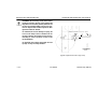
Follow this procedure to temporarily set ride height.
WARNING! To prevent possible injury and damage to
property, ensure that a vehicle is parked and the
wheels chocked before beginning this procedure.
CAUTION: Completing this procedure will
enable you to safely reach the nearest autho-
rized Peterbilt repair facility to have ride
height and pinion angle reset using the proper
equipment and technique. Do this as soon as
possible to avoid potential driveline damage.
NOTE: Suitable wheel chocks are at a minimum
an 18-inch (46 cm) long 4x4.
1. Ensure that the air supply and delivery plumbing of
the height control valve is consistent with the illustra-
tion.
NOTE: At least one of the mounting holes in the
height control valve bracket will be slotted to per-
mit rotating the valve.
NOTE: On dual-valve systems, begin with the LH
valve on the next step.
2. Loosen the fasteners mounting a height control valve to
its bracket.
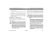
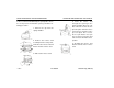
Ride Height Measurement (Location for Tandem Axles Shown)
Proprietary Rear
Air Suspension
Ride Height [inches (mm)]*
Single Drive Tandem Drive
Air Trac 11.00 (279) 11.00 (279)
Low Air Leaf 6.50 (165) 8.50 (216)
*These values are for a fully laden vehicle