
Manual

11
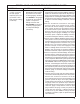
Item Description Qty.
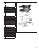
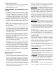
Reference Figure 8
1 5/16” Cap Screw 1
2 O-ring 1
3 5/16” Sleeve Nut 1
4 Mounting Strap 1
5 Saddle Bracket 1
6 End Cover 1
7 3/8” Cap Screw 2
8 3/8” Lock Washer 2
9 Lower Mounting Bracket 1
10 Cartridge Bolt 1
11 Desiccant Cartridge 1
12 O-ring 1
13 O-ring 1
14 Retaining Ring 1
15 Purge Valve Cartridge Assembly 1
*16 Installation Ring 1
17 O-ring 1
18 O-ring 1
19 O-ring 1
20 Retaining Ring 1
21 Heater & Thermostat Assembly 1
22 Safety Valve Assembly 1
23 Delivery Check Valve Plug 1
24 Spring 1
25 Check Valve Body (white) 1
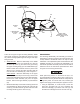
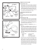
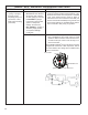
Reference Figure 9
26 Perforated Plate 1
27 Check Ring Spring 1
28 Check Valve 1
29 O-ring 1
30 Retaining Ring 1
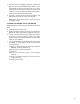
Reference Figure 10
31 Upper Bracket 1
32 Cable Assembly 1
33 Isolator 2
34 Locknut 1
35 Washer 1
29
30
26
27
SUPPLY PORT
(FROM
COMPRESSOR)
CONTROL PORT
(FROM GOVERNOR
UNLOADER PORT)
DELIVERY PORT
(TO SUPPLY
RESERVOIR)
AIR DRYER
END COVER
28
DELIVERY PORT
(TO SUPPLY
RESERVOIR)
PIPE PLUG
Old Style Bendix
®
AD-IP
®
End Cover -
Vertical Delivery Check Valve
FIGURE 9 - BENDIX
®
AD-IP
®
AIR DRYER INTERNAL COMPONENTS –
VERTICAL DELIVERY CHECK VALVE