ACom Diagnostics Diagnostic Software for ABS User Guide 5.9 ™ © 1996-2008 Bendix Commercial Vehicle Systems LLC, a member of the Knorr-Bremse Group.
INDEX General Information . . . . . . . . . . . . . . . 3 RP1210B adapters . . . . . . . . . . . . . . . . 3 PC hardware requirements. . . . . . . . . . . . 3 Technical Assistance . . . . . . . . . . . . . . . 3 Installing ACom™ Diagnostics . . . . . . . . . . 5 Uninstall ACom™ Diagnostics . . . . . . . . . . 6 Help . . . . . . . . . . . . . . . . . . . . . . . 6 Demo Mode . . . . . . . . . . . . . . . . . . . 6 Hardware Adapter Selection . . . . . . . . . . . 6 Functions of Software . . . . . . . . . . . .
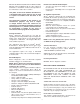
Windows 95, Windows 98, Windows NT, Windows 2000, Windows Vista and Windows XP are either registered trademarks or trademarks of Microsoft Corporation in the United States and/or other countries. Known Issues with RP1210B adapters • Tool does not support two adapters connected at the same time. • Noregon PLC - 1708 Adapter does not support USB connection.
BENDIX MAKES NO REPRESENTATION OR WARRANTY OF ANY KIND, EXPRESS OR IMPLIED, WITH RESPECT TO THE SOFT-WARE, INCLUDING WITHOUT LIMITATION, ANY WARRANTIES OF MERCHANTABILITY, FITNESS FOR A PARTICULAR PURPOSE AND NON-INFRINGEMENT, ALL OF WHICH ARE DISCLAIMED. copyright, patents or common law property rights of Bendix pertaining to the Software or Documentation.
MODIFICATIONS AND IMPROVEMENTS If the Licensee, or any of its officers, agents or employees modifies or devise any improvements in the Software or Documentation in any manner, the Licensee shall promptly disclose such modification or improvement to Bendix and Bendix shall have a nonexclusive, irrevocable, royalty free license to use such modification or improvement for any purpose including the right to grant royalty free sub-licenses thereof.
Figure 6 Install program displays that the program has been installed on the computer. Figure 8 Functions of Software Once communication has been established the program displays the Status screen.
The following information is provided regarding the ABS ECU on the status screen: ECU Information Information Displayed Explanation of information Model ABS ECU model reference such as EC-60™, TABS-6 , EC-17, EC-30™ / EC-30™T, U12, U16, 2X, A-18 Part number Bendix ABS ECU part number Serial number Bendix ABS ECU serial number Software number Bendix ABS ECU software release number ABS configuration Number of sensors and modulators the ECU is currently configured for Traction Control Displays mod
Diagnostic Trouble Code Screen The diagnostic trouble code window has three main parts: active diagnostic trouble codes, inactive or memorized diagnostic trouble codes, and event history. One or more of these tabs may not appear in the window, because they are ABS ECU dependent. All active diagnostic trouble codes (DTC’s) are displayed “real” time, which means the ABS ECU is reporting a currently active DTC. Inactive/Memorized diagnostic trouble codes are DTCs, which were active in the past.
Control Buttons Repair Launches detailed repair information for ONLY sensor and modulator DTCs. Service Data Launches the service data sheet Read Manually command a read of the ECU. This is dependent upon which tab is active. Active diagnostic trouble codes will always automatically refresh. Clear Clears the diagnostic trouble codes, depending on the active tab, this function will send a clear command for active, inactive or the event history, and information events.
Antilock The antilock section displays the current number of sensors and modulators of the system. Odometer The odometer section displays the current odometer reading. The trip odometer reading is the odometer mileage since the odometer was cleared. The service odometer is the mileage left before service is needed. Figure 18 Additional Axle for Trailer The additional axle for trailer will display if the axle is a lift or not lift axle only for configurations of 4S/2M and 4S/3M.
Configuration Diagram The diagram will reflect the typical ABS installation for the configuration read from the ABS ECU. Possible configurations are listed below. Configuration 4S / 4M Tractor 6S / 4M 6S / 5M 6S / 6M 4S / 3M Trailer 4S / 2M 2S / 1M Control will be either axle or side 2S/ 2M Tire Size Tire size is adjustable to within the limits available for the ABS ECU. Consult the tire manufacturer specifications for these values.
Brake / Engine For optimal ATC performance, both engine and brake control methods are recommended. Engine control is automatically activated to control the wheel slip of the driven axle(s). This is accomplished by sending a J1939 torque limitation request to the engine ECU. Engine control must follow SAE J1939 protocol. Bendix CVS approval is required for all new applications. Engine control is available at all vehicle speeds.
Control Buttons Start Begins calibration Stop Stops calibration Yes Acknowledges condition needed to continue No Allows condition to be met Cancel Stops calibration Close Closes dialog Wheel Speed Screen This screen allows the user to monitor wheel speeds. Along with this functionality, the user has the ability to perform data acquisition of the wheel speeds and save the results to a comma delimited file. The wheel speeds may be monitored both graphically and numerically.
Viewing Saved Data The user is able to view saved data at a later time by pressing the “Open File” button. Once the open file button has been pressed the user will be prompted to select the data file that they want to view. Figure 42 Control Buttons Open Opens saved data Close Closes the configuration screen Help Launches Help System Figure 44 Modulator Tests Given the current configuration of the ECU, a list of modulator tests will appear in the “Modulator Test Region”.
Switch Test The purpose of a given switch test is to determine if the circuit for that switch is operational. Once the test has begun, the user will be prompted to toggle the given switch to a requested position and verify the status of the switch. Switch tests listed will be based on ECU model and configuration, including Hill Start Aid if enabled on EC-60™ ECU Only.
ESP Tests The purpose of the ESP tests is to verify the operation of various ESP components. Steering angle checks the output of sensor versus the movement of the steering wheel. Yaw rate / Lateral acceleration is used to provide an indication of the vehicle lateral acceleration and rotation around the vertical axis. Primary pressure monitors the primary pressure of the air system. Secondary pressure monitors the secondary pressure of the system. Air bag sensor monitors the air bag pressure.
Figure 54 Figure 57 Installation Test NOTE: The installation test is for reference only; it does not replace the need for an automated end of line test process. Report Settings The report settings portion of Customize allows the user to save the report using the VIN as the file name and to select the folder to save the report in or the user can select to always have to enter the folder and file name for the report.
Pulse Modulator Test This test verifies whether the modulator(s) are installed correctly. The tractor and trailer pulse modulator sequence test are different. The trailer pulse modulator test will display order in which the modulators will be energized. The test energizes the modulator(s) in the predefined order: right (curbside) and left (curbside) if axle control, then right additional (if equipped) and left additional (if equipped). The tester will validate a correct response on the vehicle.
Traction Disable Test This test verifies that the traction control system can be disabled. Figure 63 Indicator Lamp Test This test shall verify the wiring of the lamp and the ABS ECU’s ability to illuminate the lamp. The tester is asked to confirm the result of the test. Figure 67 ATC Valve Test This test will verify the wiring and plumbing of the ATC valve and the ABS ECU’s ability to energize the modulator for 3.5 seconds wait 3 seconds and then re-energize the traction modulator for another 3.
Steering Angle Sensor Test This test is available only if the ABS ECU is an Advanced EC-60™. The test verifies the operation of the steering angle sensor. The user will be asked to have the steering straight for 30 seconds, then turn the steering wheel to the right ¼ turn for 30 seconds and then to the left a ¼ turn for 30 seconds. The program reads the steering angle output during the 30 seconds and displays it on the screen.
Diagnostic Switch Hill Start Aid Switch – If Hill Start Aid is enabled (EC-60™ ECU Only). The HSA switch test allow user to verify that the switch is operating correctly by toggling the switch verifying the status of the HSA lamp. Figure 74 Figure 78 Off Road Switch Hill Start Aid Lamp – If Hill Start Aid is enabled (EC-60™ ECU Only). The test will illuminate and extinguish the HSA lamp, asking the user to verify status of HSA lamp.
Scratch Pad The tester is requested to input data into the fields displayed on the screen. This data will be stored in a file for use by the program. If the ABS ECU supports scratch pad capability, a confirmation dialog will appear and ask the tester to proceed. Once the information is written, a “test complete” dialog box pops up stating “Use the Save or Print Button to Create the Report”. Figure 82 Stability Sensor This screen is available only if the ABS ECU is an Advanced EC-60™ ECU.
and writing to a specified area of memory in the ABS ECU. This allows information to be stored for OEM manufacturing data and fleet service management. Figure 86 Program information section provides the user with read only information regarding the program number of the ADL function, the ECU type the ADL program is intended for, and instruction set information. Auxiliary I/O displays which I/O the ADL function will use what type, either input or output, and the description of the ADL feature.
Known Issues with ACom™ Operation • • • • • • • Hot keys do not work with program. Older models of the EC-30T™ ECU may not support scratch pad. If user is in the installation test at the scratch pad step the program may freeze. NOTE: Stand alone scratch pad works fine. TABS-6 event history may take two clear commands to actually clear the history. Extreme graphics causes the right side and bottom of some screens to be cut off. Please change graphics back to small or 96dpi.