Installation and Servicing Instructions RD 532i/RD 537i/RD 542i combi Wall mounted condensing boiler for central heating and mains fed domestic hot water 6 720 610 893-01.TD 6 720 611 447 GB (03.
Contents Contents Safety precautions 3 Symbols 3 1 1.1 1.2 1.3 1.4 1.5 1.6 1.7 1.8 1.9 4 4 4 4 5 5 6 7 8 9 Details of the appliance EC Declaration of Conformity Standard package Description of appliance Accessories Casing dimensions Layout of appliance Function Electrical wiring diagram Technical data 6.5.2 6.5.3 6.6 6.7 6.8 6.8.1 6.8.2 6.8.3 6.
Safety precautions Safety precautions Unpacking IMPORTANT HANDLING INSTRUCTIONS If you smell gas B Turn off gas service cock at the meter. B Open windows and doors. B Do not operate any electrical switches. B Extinguish any naked flames. B Telephone your gas company. If you smell fumes from the appliance B Switch off appliance (see page 23). B Open windows and doors.
Details of the appliance 1 1.1 Details of the appliance 1.3 EC Declaration of Conformity • Wall-mounted appliance, siting not dependent on room size This appliance is in accordance with the applicable requirements of the Gas Appliance Directive, Boiler Efficiency Directive, Electromagnetic Compatibility Directive and the Low Voltage Directive.
Details of the appliance 1.4 Accessories • Standard horizontal flue kit at 100 mm outside diameter for flues up to 4 m in length (3.5m for the R 40 HE). • Flue duct kits for horizontal (125 mm outside diameter) for flue lengths up to 13m or 10m (RD537i & RD542i) and vertical flue systems for flue lengths up to 13.7m or 10.7m (RD537i & RD542i). Fitting instructions are sent with these kits. 1.5 Casing dimensions min . min .
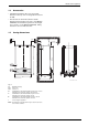
Details of the appliance 1.6 Layout of appliance 120 221.1 221.2 27 226 20 102 32.1 29 36 271 6 415 43 9 63 416 358 396 64 18 7 423 418 355 6.1 15 8.1 88 400 295 4 98 6 720 610 599 - 00.TD Fig. 2 4 6 6.1 7 8.1 9 15 18 20 27 29 32.
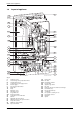
Details of the appliance 1.7 Function 26 27 29 226 229 33 30 36 32 J 20 221 6 35 29.1 9 63 52.1 69 64 52 56 317 61 4 400 358 7 55 355 18 88 57 8.1 ECO 3 0 2 1 4 5 96 95 90 E max 6.1 J 43 44 97 98 46 45 42 3 M 93 91 13 15 94 max 84 47 6 720 610 59703.2O Fig. 3 4 6 6.1 7 8.1 9 13 15 18 20 26 27 29 29.1 30 32 33 35 36 43 44 45 46 47 52 52.
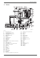
Details of the appliance 1.8 Electrical wiring diagram o - orange g - green bl - black r - red p - purple 33 365 364 61 317 366 363 367 ECO 4.1 25 V 153 230V/AC 230 V 310 136 400 135 312 328 313 151 124 789 p p p L N Ns Ls LR 302 300 161 84 3 4 F M 96 328.1 9 18 M M 422 g 6 g 226 o o r r mains supply 52 o 52.1 56 o bl bl bl bl 36 bl 6.1 32 6 720 610 602 - 02.1O Fig. 4 4.1 6 6.1 9 18 32 33 36 52 52.
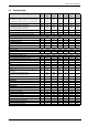
Details of the appliance 1.9 Technical data Units RD 532i RD 532i RD 537i RD 537i RD 542i RD 542i NG Propane NG Propane NG Propane 41.4 41.4 39.1 40.0 12.9 12.8 11.4 11.8 39.1 40 41.4 41.4 39.1 40.0 16.2 16.1 14.3 14.8 39.1 40 Max. rated heat output net 40/30°C central heating Max. rated heat output net 50/30°C central heating Max. rated heat output net 80/60°C central heating kW kW kW 34.3 34.0 32.2 34.3 34.0 32.3 39.7 39.2 37.1 39.7 39.2 37.1 Max. rated heat input net Min.
Installation regulations Condensate analysis, mg/l Ammonium 1.2 Domestic water performance Nickel 0.15 ≤ 0.01 Mercury Cadmium ≤ 0.001 Sulphate Chromium ≤ 0.005 Zinc ≤ 0.015 Halogenated hydrocarbons Tin ≤ 0.002 ≤ 0.01 Hydrocarbons 0.015 Vanadium Copper 0.028 pH-value Lead ≤ 0.0001 1 R 30 HE R 35 HE R 40 HE Temperature Rise 30 °C 14.2 17.0 19.2 Temperature Rise 35 °C 12.1 14.6 16.4 Temperature Rise 40 °C 10.6 12.8 14.4 Maximum Mains pressure bar 10.0 10.
Installation 3 Installation B Always turn off the gas cock before carrying out any work on components which carry gas. i 3.1 Fixing of the appliance, gas and flue connections, commissioning of the system and electrical connections may only be carried out by competent persons authorised by CORGI. Important remarks B Appliance should only be installed in sealed central heating and hot water systems. B To avoid gas formation in the system, galvanised radiators or pipes must not be used.
Installation requirements of BS2767:10. Fit Thermostatic Radiator Valves to radiators in the sleeping accommodation and not to the radiator where the room thermostat is sited, this must be left open. Repeated venting probably indicates a leak and this must be rectified to ensure the proper operation of the appliance. No galvanised radiators or pipes must be used. If any system water treatment is required then only products suitable for use with Aluminium shall be used i.
Installation 3.5 Wall mounting frame assembly B Take the wall mounting frame out of the package and screw together with 6 screws as shown in fig. 7. Use the inner lugs on the top and bottom horizontal sections. B Screw the pre-plumbing manifold with two screws to the wall mounting frame. 6 720 610 597-08.1O Fig. 9 6 720 610 597-06.1O Fig. 7 3.6 Pre-piping the system 200 B Hold the wall-mounting frame against the wall ensuring that it is vertical.
Installation Condensate Termination and Route External condensate pipework The appliance has a built-in syphonic condensate trap eliminating the need for external traps. Connect to the 22mm plastic drain pipe and extend the pipe run away from the control panel and appliance witha constant fall of 2.5° or 25mm in every metre. See Fig. 12 The syphonic condensate trap collects condensate into a trap which releases it in 100 ml quantities. This helps to prevent the discharge from freezing.
Installation Fixing the appliance B Fit the washers onto the gas and water connections. B Lift the boiler onto the wall-mounting frame. The lugs pass through the rectangular holes in the boiler back panel. The flue system must be installed in accordance with the requirements of BS5440:1. Standard 100 mm flue system B Take care not to disturb the washers on the connections. The standard concentric flue system provides for a horizontal length of up to 4m (3.5m RD542i).
Installation 3.9.1 lighting, activated by passive infra-red sensing heads. If the terminal is less than 2 m above a surface to which people have access then a guard must be fitted. The guard must be evenly spaced about the terminal with a space of 50 mm in each direction and fixed with plated screws. A guard Type K6 for the standard horizontal flue, can be obtained from Tower Flue Components, Vale Rise, Tonbridge TN9 1TB.
Installation 3.9.2 Installation of the flue The standard 100 mm diameter horizontal flue system is suitable for lengths up to 4m (3.5m RD542i). Flues up to 650 mm do not require an extension duct assembly. Flues between 1600 mm and 4000 mm (3500 mm RD542i) require extension duct assemblies. NOTE: Flue lengths between 650 mm and 730 mm cannot be accommodated. Refer to fig. 17, 18, 19.
Installation Maximum 1600mm Outer Wall Flue Turret Terminal Assembly Extension Duct Clamp 6 720 610 599 - 00.TD Fig. 18 Flue with One Extension Outer Wall Flue Turret Clamp Extension Duct Clamp Extension Duct Clamp Terminal Assembly 6 720 610 599 - 01.TD Fig. 19 Flue with Extensions Flue Turret Clamp Flue Terminal Extension Flue Duct Wall Sealing Gasket 6 720 610 599 - 01.TD Fig. 20 Flue Components 3.9.3 Flue duct preparation and assembly Measure the flue length L. Refer to fig.
Installation Outer Wall Face L Flue Terminal 120 Wall Sealing Gasket 6 720 610 599 - 01.TD 6 720 610 599-00.TD Fig. 21 Flue length - rear Fig. 23 Flue terminal position Assemble flue system completely. Push the ducts fully together and clamp in the positions. The slope of the terminal outlet must be directed as per Fig. 23. The assembly will be made easier if a solvent free grease is lightly applied i.e Silicone lubricant, to the male end of the ducts.
Electrical connections 4 Electrical connections B Always disconnect the power supply to the appliance at the mains before carrying out any work on the electrical systems and components. B Allow mains cable to protrude at least 50 cm from wall. B To maintain the splash-proof (IP) design: cut the cable grommet hole size to match the diameter of the cable, see fig. 27. B The appliance must be earthed.
Electrical connections B Cut cable grommet to diameter of cable. 3 0 4 2 Mains Voltage external controls connections Externally wired controls are not required; the boiler has a built-in text display programmer and frost protection. The TR2 room thermostat provides additional frost protection and compliance to Part L of the Building Regulations. 5 1 4.3 E 8-9 5-7 10-12 13-14 6 720 610 332-12.1R Fig. 27 B Feed cable through cable grommet and connect the mains supply cable, see fig. 28.
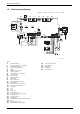
Commissioning 5 Commissioning 27 136 365 61 317 366 367 358 ECO 363 310 400 364 8.1 135 E 295 15 170 nn . 171 172 173 170 6 720 610 597 - 05.1O Fig. 30 8.
Commissioning B Before commissioning, the gas supply pressure must be checked at the gas supply pressure test point (see page 6, fig. 2, item 7). Natural gas appliances must not be operated if the gas supply pressure is below 18 mbar or above 24 mbar. LPG appliances must not be operated if the supply pressure is not 37 mbar at the inlet to the appliance. Switching off the appliance B Set the master switch to (0). The green indicator lamp goes out.
Commissioning 5.5 Setting the domestic hot water temperature and flow rate 5.5.1 Domestic hot water temperature B To reduce the flow rate (min. 8 l/min): turn screw on flow switch clockwise (–). The outlet temperature will increase relative to the decrease in the flow rate. The hot water temperature can be set to between approx. 40 °C and 60 °C. This temperature is not shown on the display. 6720 610 332-25.1O 6 720 610 333-07.1O Fig. 34 Fig. 33 5.
Commissioning 5.9 i Fault Condition A list of faults that may occur is given on page 46. In the unlikely event of a fault occuring while the appliance is in operation: The display and the textdisplay then show a fault code and the button may also flash. If the button 7. Wait until GREEN LED flashes 3 seconds ON and 1 second OFF. The gateway has now Created the House Address. 8. Make the jumper JP1 on the ADM while powering up the appliance, see Fig. 36. Observe LED on ADM flashing.
Text Display B To start programming, press any button, e. g. . The display lighting switches on and the main menu is displayed: 6 Text Display 6.1 General Description T • The text display is used to display information about the appliance and the system and to alter the settings displayed. • Once the appliance has been in operation for one day, the text display module has a power buffer period of about 10 hours during which it will run without the mains power supply.
Text Display B Press the button to confirm the setting. The cursor then returns to the top line. 6.3 B Press the button to confirm the setting and return to the previous menu (fig. 39 page 26). -orB Do not press any other buttons for 15 minutes. Deleting a setting Main menu 28 Holidays - - Days holiday 28 Heating program - - - Day - 1st operating mode - 1st switching point ... - 6th switching point 28 Set econ- omy temp. (if TR2 is connected) - 5...
Text Display 6.4 Setting the time/day 6.4.1 Setting the time and day For details of how to set the time and day, refer to page 26. i 6.4.2 Changing winter and summer time: B Only adjust the clock! Do not alter the switching points (for heating, economy, etc.). Holidays In the Holiday programme, the central heating runs in Economy mode and the hot water is switched off (frost protection function remains active).
Text Display 6.5.2 Setting the Economy temperature (if TR2 is connected) This option allows you to set the room temperature for Economy mode (Off (Economy)). 6.7 i Info B Select Info from the main menu.
Text Display 6.8 Settings Time correction: 6.8.1 Heating (if TR 2 is connected) Optimum Start B Press and hold the button (about 5 seconds) until the display shows Time correction and LCD contrast. If the optimum start facility is used: B Press Set the heating ON time to 1 hour before the house needs to be at the required temperature. B Press the value. The boiler will start in heating mode at the optimum time, which could be at any time during that hour. B Press or 24 hours.
Individual settings 7 Individual settings 7.1 Mechanical settings 7.1.1 Checking the size of the expansion vessel Maximum pressure at maximum CH flow temperature is 2.5 bar. If the pressure is greater than this then fit an extra expansion vessel. Refer to table 12. System Capacity – BS7074:1 Expansion Vessel Pressure and System Capacity Control setting CH flow temperature 1 2 3 4 5 E max approx. 35°C approx. 43°C approx. 51°C approx. 59°C approx. 67°C approx. 75°C approx.
Individual settings Setting service functions 7.2.4 Only the service functions that can be set are displayed. B Press any button to activate the main menu. B Press or button until the arrow cursor is pointing to Settings. B Press the button. B Press oder button until the arrow cursor is pointing to Service. B Press the button. The cursor is pointing to Display service parameters.
Converting the appliance to different gas types 8 Converting the appliance to different gas types The setting is factory sealed at maximum. Adjustment to the rated heat input and min. heat input is not necessary. Checking the gas supply pressure B Check the gas supply pressure at the gas supply pressure testing point. i Natural gas appliances must not be operated if the gas supply pressure is below 18 mbar or above 24 mbar.
Converting the appliance to different gas types B Press normal. or until the display shows B Press the button. The text display shows Store settings. 63 B Press B Press the to select yes. button. B Remove testing probe from the flue gas testing point (234) and refit sealing plug. B Re-seal gas valve adjusting screw and gas flow restrictor. 6 720 610 332-64.1R Fig. 43 RD532i Gas Type Natural gas type G20 LPG G31 (propane) CO 2 reading at max. rated heat output CO 2 reading at min.
Converting the appliance to different gas types 8.2 Testing combustion air/flue gas at set heat output 8.2.1 Testing the O 2 or CO2 level in the combustion air i By testing the O2 or CO2 level in the combustion air the gas tightness of a type C13, C33 flue system can be checked. The O2 level must not be less than 20,6 %. The CO2 level must not exceed 0,2 %. B Press and hold the button until the display shows – –. “Chimney sweep” mode is now active.
Maintenance 9 Maintenance B Always disconnect the appliance from the electrical power supply (fuse, circuit breaker) before carrying out any work on the electrical systems or components. B Always turn off the gas cock before carrying out any work on components which carry gas. i There is a Service booklet for the Engineer, order no. 7-181-465-349, available to competent persons. i All safety and control systems are monitored by the Bosch Heatronic.
Maintenance 9.1 Pre-Service Check List Date 1 Call up the last fault stored by the text display, (see page 30). 2 Check ionisation current, Service Function 3.3, (see page 38). 3 Perform visual check of air/flue duct. Visual check of diaphragm for soiling and splits (see page 40). 4 Check gas supply pressure (see page 33). 5 Test combustion air/flue gas (see page 35). 6 Check CO2 setting for min./ max. (gas/air ratio) (see page 33). mbar min. % max.
Maintenance 9.2 Description of servicing operations The combustion performance must be checked before and after any servicing work on the combustion and burner components. Refer to section 8.2. B Check control pressure on the air - gas mixer unit at max. rated heat output using an electronic manometer. Checking the ionisation current, Service Function 3.3 B Select Service Function 3.3.
Maintenance B Loosen any deposits in the heat exchanger from top to bottom using the cleaning blade. Refer to fig. 49. Burner B Check that the gas cock is turned off and the master switch is in the OFF position B Remove the clips (1) and unscrew the two bolts (2). Refer to fig. 52. B Unscrew and remove the two hexagon screws securing the fan (3). B Slacken fully the rear securing bolt (4). B Remove the burner coverplate. 4. 6 720 610 332-73.1R 2. Fig.
Maintenance Condensation trap In order to prevent spillage of condensate the condensation trap should be completely removed, (see page 38, fig. 48). B Unscrew condensation trap and check connection to heat exchanger is clear. B Remove condensation trap cover and clean. The flaps of the diaphragm (443) must open upwards. i B Seal the mixer unit (29). Diaphragm in mixer unit for RD537i/542i B Remove fan and mixer unit assembly. B Fill condensation trap with approx. 1/4 l of water and refit.
Maintenance Siphon 9.3 B Unscrew the clip and disconnect the pipe to the siphon. Before changing any components check that the gas is turned off and that the appliance is electrically isolated. When necessary close the system valves and drain the appliance. B Remove the drain plug to drain the siphon. B Unscrew the securing nut from beneath the side facia and remove the siphon. Refer to figure below. B Refit and prime the siphon.
Maintenance B Remove the pcb control board. 9.3.2 Fan Assembly 3. 2. 4. 7 181 465 330-10.1R Fig. 58 Fuses B Remove the connections covers. Refer to fig. 25, 26. The fuses are located adjacent to the mains connector block and connector ST18. Refer to fig. 4. Fuse, item 312, is only replaceable by removing the pcb. 1. 7 181 465 330-05.1R Fig. 59 B Switch off the appliance. B Undo lower pipe union on gas pipe (1.). Refer to fig. 59. B Remove fan lead and earth connector (2.).
Maintenance B Remove 3-way valve. Alternatively B After removing the siphon release the four Allen screws and remove and replace the pump head. 1. 1. 2. 3. 7 181 465 330-03.1R 5. 4. 7 181 465 330-12.1R Fig. 61 After refitting: B Fill system, bleed and re-pressurise (see Installation Instructions). 9.3.5 Fig. 60 9.3.4 3-way diverter valve motor B Switch off the appliance. 3-way diverter valve B Switch off the appliance. B Disconnect appliance from the power supply. B Turn off service cocks.
Maintenance Domestic Hot Water Temperature Sensor – Item 6.1, fig. 2 9.3.8 B Check that the inlet water valve is closed and the domestic hot water circuit is drained. B Use new seals when fitting the new heat exchanger. B Release and pull-off the connector. 9.3.9 B Unscrew the sensor. B Refer to section 9.2. 9.3.7 Gas Valve Domestic Hot Water Heat Exchanger B Refer to section 9.2. Electrode assembly B Use a new seal if the existing seal is damaged. B Check that the gas cock is turned off. 9.
Maintenance 9.3.14 Flow switch B Shut the mains water inlet valve and drain the domestic hot water circuit. B Pull-off the connectors from the micro-switch. B Unscrew the inlet and union connection and remove the assembly. B Transfer components, as necessary, to the new heat exchanger. B Ensure that all the seals are in place and all of the connections are tight before re-commissioning the appliance. B Reset the domestic hot water flow rate on the new assembly. OUTLET INLET 6 720 610 602 - 05.10 Fig.
Appendix 10 Appendix 10.1 Fault Codes More detailed fault finding procedures are described in the Service Booklet for the Engineer number 7 181 465 347. Display code Description Remedy A1 pump has run dry Check system pressure, add water and bleed system as necessary A7 Hot water NTC sensor defective. Check hot water NTC sensor and connecting lead for circuit breaks/short circuits. A8 Break in communication Check connecting lead to TR2 b1 Code plug not detected.
Appendix 10.2 Short parts list Key Description Qty GC Spare part number 1 Sensor - Flue gas temp. 1 8 722 963 858 0 2 Sensor - CH flow temp. 1 8 714 500 087 0 3 Sensor - DHW flow temp. 1 8 714 500 054 0 4 Control board pcb 1 8 748 300 495 0 5 Gas valve ZWBR 8-30 1 8 747 003 516 0 5.
Appendix 10.3 Heating/hot water output settings RD532i N.G. 10.5 Heating/hot water output settings RD537i N.G. Natural gas G20 Natural gas G20 Display code Heat output, kW Heat input, kW Gas vol. flow rate (l/min at tV/t R = 80/60°C) Display code Heat output, kW Heat input, kW Gas vol. flow rate (l/min at tV/tR = 80/60 °C) 30 9.1 9.2 16.0 30 11.1 11.3 19.7 40 12.1 12.2 21.4 40 14.9 15.0 26.3 50 15.1 15.3 26.7 50 18.6 18.8 32.8 60 18.1 18.3 32.0 60 22.3 22.5 39.
6 720 611 447 GB (03.11) Green light ON. Repeats 5 times (N.G.) or 3 times (L.P.G.) before lock-out. Mains switch ON. Pump ON Diverter valve operates. Hot water demand. Ignition spark 5 secs Ignition sequence Pre-heat mode.** Ignition spark 5 secs Fan runs to purge gas from burner. No Burner lights. Red light ON. Pump ON Diverter valve operates. Yes Heat input modulates to maintain the delivery temperature. Over temperature shut down if water temperature is 8°C above set value.
Mains switch ON. 50 Repeats 5 times (N.G.) or 3 times (L.P.G.) before lock-out. Green light ON. CH demand. Ignition spark for 5 seconds. Ignition sequence Room thermostat and/or mains programmer or link ON AND Electronic facia programmer (if fitted) ON AND CH control knob ON. Fan runs to purge gas from burner. No Burner lights. Red light ON. Pump ON Fan to start speed. Gas valve opens. Yes Burner remains OFF until flow temperature is below set value. Fan speed reduces over 15 secs.
Appendix 6 720 611 447 GB (03.
Appendix EXCELLENCE COMES AS STANDARD Manufactured exclusively for British Gas by The Bosch Group Bosch Group, Worcester Heat Systems, Cotswold Way, Warndon, Worcester WR4 9SW.
Users Instructions and Customer Care Guide RD 532i/RD 537i/RD 542i combi Condensing boiler RD 430i system Condensing boiler 6 720 610 598 - 00.2O 6 720 610 604 GB (03.
Contents Contents Excellence comes as standard 4 Safety precautions 5 1 General notes 7 2 Controls 11 3 3.1 3.2 3.3 3.4 3.5 3.6 3.7 3.8 3.9 Operating the Appliance Preparation Switching the Appliance On/Off Switching on the Central Heating Controlling Central Heating Combination Boilers: Setting Hot Water Temperature System boiler with Storage Tank Summer Mode, Hot Water Only (Combi Appliances) Frost protection (Combi Appliances) Fault Condition 12 12 14 15 15 16 17 18 19 19 4 4.1 4.2 4.2.1 4.
Contents 4.5.1 4.5.2 4.5.3 4.6 4.6.1 4.6.2 4.7 4.8 4.8.1 4.8.2 4.8.3 4.
Excellence comes as standard Excellence comes as standard Thank you for purchasing an RD 532i/RD 537i/RD 542i /RD 430i condensing appliance. The RD 532i/RD 537i/RD 542i /RD 430i Series has been developed by the Bosch Group and the strictest quality control standards are demanded throughout every stage of production. Indeed, the Bosch Group have led the field in innovative appliance design and performance for many years.
Safety precautions Safety precautions Gas Safety (Installation and Use) Regulations 1998 It is the law that all gas appliances are installed by a competent person in accordance with the above regulations. Failure to install appliances correctly could lead to prosecution. It is in your interest, and that of safety, to ensure compliance with the law. If you smell gas: B Turn off gas service cock at the meter. B Open all doors and windows. B Do not operate any electrical switches. B Do not smoke.
Safety precautions Combustible materials B Do not store or use any combustible materials (paper, thinners, paints etc.) in the vicinity of the appliance. Health and safety B This appliance contains no asbestos products. B There is no potential hazard due to the appliance being electrically unsafe. B There are no substances used in the construction that are a potential hazard in relation to the COSHH Regulations (Control of Substances Hazardous to Health Regulations 1988).
General notes 1 General notes To get the best from your appliance please read these instructions carefully. Sealed heating systems The appliance is fitted to a sealed heating system which is prepressurised. Your installer will tell you of the minimum and maximum pressure which must be indicated on the pressure gauge. Check regularly that the pressure is maintained and contact your installer or maintenance engineer if there is a permanent significant drop in the pressure.
General notes Clearances Your installer will have provided adequate space around the appliance for safety and servicing access. Do not restrict this space with the addition of cupboards, shelves etc. next to the appliance. Left-hand side Right-hand side In Front Above Casing (Vert. Flue) Above Flue Turret Below 10 mm 10 mm 600 mm 75 mm 30 mm 200 mm Table 1 Room thermostat A room temperature controller is may be fitted to control the central heating.
General notes With all mains fed systems the flow of water from individual taps will vary with the number of outlets operated simultaneously and the cold water mains supply pressure to the property. Flow balancing using “ball-o-fix” type valves is recommended to avoid an excessive reduction in flow to individual outlets. For further information contact British Gas Technical Services Department.
General notes Do not allow the flue terminal fitted on the outside wall to become obstructed or damaged. Pump The pump is a fully modulating type to which the parameters have been set by the manufacturer and must not be adjusted. 10 6 720 610 604 GB (03.
Controls 2 Controls 136 365 61 317 366 367 363 310 400 ECO 364 8.1 135 295 170 171 172 173 170 6 720 610 598 - 01.2O Fig. 1 8.
Operating the Appliance 3 Operating the Appliance 3.1 Preparation Turn on the gas cock (172). B Press in the handle and turn it anti-clockwise as far as the stop (when handle is in line with direction of flow, the cock is open). Central heating system valves (170) B Using a spanner, turn square nut until groove is in line with direction of flow (see detail). Groove at right angles to direction of flow = off. Cold water inlet valve (173) B Turn handle so that it is in line with direction of flow.
Operating the Appliance Check the central heating system pressure B The pointer on the pressure gauge (8.1) should be about 1 bar. B If the pointer is below 1 bar (when the system is cold), top up the system with water until the pointer is 1 bar. Your installer will have shown you how to do this. B The maximum operating pressure of 2.5 bar at maximum central heating flow temperature must not be exceeded. If the pressure increases to 3 bar then the relief valve (15) opens. 2 3 1 4 0 bar 8.
Operating the Appliance 3.2 Switching the Appliance On/Off Switching on B Switch on the appliance at the master switch (I). The indicator lamp shows green and the display will show the central heating flow temperature, when the appliance is operating in the central heating mode. 6 720 610 333-04.1O Fig. 4 i If the display alternates between -II- and the central heating flow temperature, the trap filling programme is active.
Operating the Appliance 3.3 Switching on the Central Heating B Turn the central heating temperature control level: to the desired – “Min” setting: 35°C – Low-temperature heating: setting “E” (approx. 75°C) – “Max” setting: 88°C When the burner is lit, the red indicator lamp is illuminated. 6 720 610 333-05.1O Fig. 5 3.4 Controlling Central Heating B Set the timer to the correct time. B Set room thermostat to the desired room temperature. B Set temperature driven control unit, if fitted.
Operating the Appliance 3.5 Combination Boilers: Setting the Hot Water Temperature Hot water temperature On combi models, the hot water temperature can be set to between approx. 40°C and 60°C using the temperature control . The domestic hot water temperature is not shown on the display. 6 720 610 333-07.1O Fig. 6 Control Setting Water Temperature Anti-clockwise limit approx. 40°C approx. 55°C Clockwise limit approx.
Operating the Appliance ECO mode with demand detection, button is lit The demand detection function enables maximum gas and water economy. Briefly turning a hot water tap on and then off again signals demand to the appliance which then heats up the water to the set temperature. Hot water is thus available in about 1 minute. ECO mode, button is lit Water is not heated up until hot water is drawn. This means that there is a longer waiting period before hot water is available. 3.
Operating the Appliance Control Setting Water Temperature Anti-clockwise limit approx. 10°C (frost protection) l approx. 60°C Clockwise limit approx. 70°C Table 3 ECO button Pressing and holding the ECO button , until it lights up switches from Comfort mode to ECO-mode. Comfort mode, ECO button is not lit (factory setting) In Comfort mode the hot water tank has priority. The hot water cylinder is first heated up to the set temperature. The appliance then switches to central heating mode.
Operating the Appliance 3.8 Frost protection (Combi Appliances) B Leave master switch switched on. If the appliance is to be left for long periods switch the central heating on and set the room temperature controller at 6°C. B Add a suitable anti-freeze fluid to the water in the central heating system. Suitable products are available from Betz-Dearborn Tel.: 0151 4209563, Fernox Tel.: 01799 550811 and Salamander Tel.: 0121 378 0952. 3.
Text Display 4 Text Display 4.1 General Description • The text display is used to display information about the appliance and the system and to alter the settings displayed. • Once the appliance has been in operation for one day, the text display module has a power buffer period of about 10 hours during which it will run without the mains power supply. After that period has elapsed, the clock function shuts down but all other settings are retained. 4.2 Programming a b c C 6 720 610 337-08.
Text Display • Domestic Hot Water temperature (System boiler if a Storage Tank is accorded). Additional indication if a special programme is active: • x holidays • Hot water immediately • Constant on (comfort, if TR2 is not connected) • Constant off (economy, if TR2 is not connected). Other special operating modes may be displayed during commissioning, servicing, etc. The programming procedure is described in detail below using the clock function as an example: B To start programming, press any button, e.
Text Display B Confirm the selection by pressing the The corresponding submenu is displayed: button. T 6 720 610 598-05.2O Fig. 10 Submenu: Time/day In the submenus, the top line indicates what action is required. The bottom line shows the previous menu level, if applicable (see Fig. 10). B Use the or button to select Time/day. B Confirm the selection by pressing the The corresponding submenu is displayed: button. H T 6 720 610 598-06.2O Fig.
Text Display B Use the or button to set the minutes. B Confirm the setting by pressing the B Use the or button. button to set the day of the week. B Press the button to confirm the setting. The cursor then returns to the top line. -orB Press the button to confirm the setting and return to the previous menu (Fig. 9 page 22). -orB Do not press any other buttons for 15 minutes. 4.2.1 Deleting a setting Either overwrite the setting or press the C button to delete it. B Find the setting to be deleted.
Text Display 4.3 Menu structure Main menu 1. Time/day/hol- Time/day idays Heating Hot water Info 24 2. - 3. - - - Set econ- omy temp. (if TR2 is connected) Manual (if TR2 is not connected) - Hot water program - - Hot water immediately - Holidays Heating program - Parameters to change/select - Hours - Minutes - Day of week Days holiday - Day - 1st operating mode - 1st switching point ... - 6th switching point 5...
Text Display Main menu Settings 1. Heating Hot water (System boiler-models) Service Page Submenu 2. - 3. - Parameters to change/select Optimum Start Off/On 33 Only charging times/ 30 times and temperatures Display service param. Further options - - 33 Language -English/ -Français/ -Deutsch -Time correction -LCD contrast - 34 - 35 Operating times Fault history 4.4 Setting the time/day 4.4.1 Setting the time and day 34 34 34 For details of how to set the time and day, refer to page 21.
Text Display ically cancels Economy mode at midnight on the last day and returns to Automatic mode. i The day on which you enter the days holiday counts as the first day of the holiday, i.e. the unit starts the holiday program immediately. Only include the day on which you are returning if you don’t want the heating to return to the normal program on that day! To cancel Holiday mode early: B In the Holidays submenu: Press the C button until the display shows 0 . 26 6 720 610 604 GB (03.
Text Display 4.5 Heating 4.5.1 Heating program Basic setting (Automatic mode) • The appliance switches automatically between normal heating, Economy mode and Frost protection mode according to the timer settings entered. • Basic setting: – Heating starts at 6:00 am – Economy starts at 10:00 pm Setting options • Maximum of six switching points per day with three different operating modes (Heating, Economy, Frost protection). • Same times for Monday to Friday. • Same times for Saturday and Sunday.
Text Display B Press . The display shows Set 1. operating mode. B Set the desired first operating mode (Heating, Economy or Frost protection). B Press . The display shows Set 1. time period. B Set the desired first time period. B Press . Set the following operating modes and time periods as described for the first. B If necessary: select the next day and enter the operating modes and timer periods as described above.
Text Display 4.5.3 Manual operating mode (if TR2 is not connected) For selecting an operating mode that is different from the one set in the heating programme (Automatic mode). • You can choose between Automatic, Constant on (comfort) and Constant off (economy). • The manually selected operating mode starts immediately. • Constant off (economy) and Constant on (comfort) are automatically reset at 00.00 (midnight).
Text Display 4.6 Hot water General description • Combi models only: The basic settings provide a straightforward timer programme: enabled from 5:00 am, disabled from 10:00 pm. The ECO button must not be lit (Comfort mode). • System models (with Storage Tank): The basic settings provide a timer programme: enable from 5:00 am, disable from 10:00 pm. With the menu Hot water (see page 33) you can choose a timer-/temperature programme with the basic settings: 60°C from 5:00 am, 10°C from 10:00 pm.
Text Display 4.6.1 Hot water program • Up to six switching points per day can be set. • There are two operating modes: Blocked and Released. B From the main menu, select Hot water and then from the first submenu, select Hot water program. B Set the days of the week, Blocked/Released (operating mode) in the same way as for the switching points and modes for heating as described on page 27. 4.6.2 Hot water immediately (System models) • Hot water immediately ON: – Comfort mode is active for 2 hours.
Text Display 4.7 i Info B Select Info from the main menu. You can view the following information: Display text Description Room temperature (if TR 2 connected) Current temperature in the room where TR 2 is installed Required room temperature (if TR 2 connected) Required temperature in room where TR 2 is installed Operating mode (if TR 2 connected) E. g. Heating, Economy in Automatic mode or Economy, Heating, Frost protection in manual mode Max. flow temp.
Text Display 4.8 Settings 4.8.1 Heating (if TR 2 is connected) Optimum Start B From the main menu, select Settings and from the first submenu, select Heating. B Press 4.8.2 or to switch Optimum Start on or off. Hot Water (Storage Tank, System boiler models only) The text display can control the hot water either with Times and temperatures or only times. • Times and temperatures: One can choose up to six different times with temperatures, see page 30 “Hot water”.
Text Display Service parameters Language Available languages are: English, Français (French), Deutsch (German). B From the main menu, select Settings, from the first submenu select Service, from the Second submenu select Further options, and from the third submenu select Language. B Press or to select the desired language. Two other supplementary functions can be selected from the third submenu Language: • Time correction • LCD contrast.
Text Display water) since commissioning. B From the main menu, select Settings, from the first submenu select Service, from the Second submenu select Further options, and from the third submenu select Operating times. Fault history This option displays any faults that have occurred for the information of the service engineer. The first fault displayed may still be active. Any other faults displayed are no longer active.
Text Display 4.9 Individual timer programmes Heating periods for central heating Time Operating mode 6. Time Operating mode Time 5. Operating mode 4. Time Operating mode 3. Time Operating mode 2. Time Status 1. Operating mode Switching point Monday Tuesday Wednesday Thursday Friday Saturday Sunday Enable/disable hot water function Time Operating mode 6. Time Operating mode Time 5. Operating mode 4. Time Operating mode 3. Time Operating mode 2. Time Status 1.
Fault finding 5 Fault finding Problem Cause Remedy Desired room temperature is not reached Thermostatic valve(s) set too low Increase thermostatic valve setting(s) Temperature control for CH flow set too low Increase CH flow temperature control setting Air trapped in heating system Bleed radiators and heating system Desired room temperature exceeded by large amount Radiators are too hot Turn down thermostatic valves Temperature rises instead of falling Clock is incorrectly set Check settin
Tips on saving energy 6 Tips on saving energy Heating economically The boiler is designed to provide a high level of comfort while keeping gas consumption and the resulting environmental effect as low as possible. The gas supply to the burner is controlled according to the level of demand for heat. The boiler continues to operate with a low flame if the demand for heat reduces. The technical term for this process is modulating control.
General Information Hot water A lower setting on the hot water temperature control can result in considerable energy savings. For combi appliances: The on-demand activation using the ECO-button makes possible the maximum savings of gas and water. Now you know how to heat your home economically with the RD 532i/RD 537i/RD 542i /RD 430i gas condensing boiler. If you have any other questions, please contact your installer – or write to us.
Maintaining your appliance 8 Maintaining your appliance Your new RD 532i/RD 537i/RD 542i /RD 430i gas-fired appliance represents a long-term investment in a reliable, high quality product. In order to realise its maximum working life, and to ensure it continues to operate at peak efficiency and performance, it is essential that your boiler receives regular, competent servicing and maintenance checks beyond the initial 2 year guarantee period.
Fault or breakdown 10 Fault or breakdown This product is supported in the UK by Worcester Heat Systems Ltd. – part of the Bosch Group. A specialist factory trained field SERVICE ENGINEER is available to attend a breakdown or manufacturing fault occuring on this appliance. No charge will be made for parts and/or labour providing: • An appliance fault is found and the appliance has been installed within the past 24 months. Reasonable evidence of this must be supplied on request.
Your guarantee 11 Your guarantee This appliance is guaranteed against faulty material or workmanship for a period of 24 calendar months from the date of installation subject to the following conditions and exceptions. • That during the currency of this guarantee any components of the unit which are proved to be faulty or defective in manufacture will be exchanged or repaired free of material charges and free of labour charges by Worcester Heat Systems Limited.
Guarantee registration 12 Guarantee registration You should complete and return the postpaid Guarantee Registration Card within 14 days of purchase. The card will register you as the owner of your new RD 532i/RD 537i/RD 542i /RD 430i appliance and will assist us in maintaining an effective and efficient customer service by establishing a reference and permanent record for your boiler. This will not affect your statutory rights in any way. Important: For your own record: Model ............................
13 Operating Instructions Quick Reference Switching on 6 720 610 333-04.1O Switching the central heating on 6 720 610 333-05.1O Text Display Set switching times and operating mode within the text display. Hot water temperaeture – Combination boiler only 6 720 610 333-07.1O “ECO”-button lit – Economy mode. “ECO”-button not lit – Comfort mode Refer to page 19. Fault Condition Switching off 6 720 610 333-11.
Users Instructions and Customer Care Guide RD 532 Condensing boiler RD 428 Condensing boiler 6 720 610 577-01.10 6 720 610 600 GB (03.
Contents Contents Excellence comes as standard 4 Safety precautions 5 1 General notes 6 2 Controls 10 3 3.1 3.2 3.3 3.4 3.5 3.6 11 11 14 15 15 15 3.7 3.
Contents 8 Fault or breakdown 23 9 Your Bosch guarantee 24 10 Guarantee registration 25 11 Operating Instructions Quick Reference 27 6 720 610 600 GB (03.
Excellence comes as standard Excellence comes as standard Thank you for purchasing an RD 532/RD 428 condensing appliance. The RD 532/RD 428 Series has been developed by the Bosch Group and the strictest quality control standards are demanded throughout every stage of production. Indeed, the Bosch Group have led the field in innovative appliance design and performance for many years.
Safety precautions Safety precautions Gas Safety (Installation and Use) Regulations 1998 It is the law that all gas appliances are installed by a competent person in accordance with the above regulations. Failure to install appliances correctly could lead to prosecution. It is in your interest, and that of safety, to ensure compliance with the law. If you smell gas: B Turn off gas service cock at the meter. B Open all doors and windows. B Do not operate any electrical switches. B Do not smoke.
General notes Combustible materials B Do not store or use any combustible materials (paper, thinners, paints etc.) in the vicinity of the appliance. Health and safety B This appliance contains no asbestos products. B There is no potential hazard due to the appliance being electrically unsafe. B There are no substances used in the construction that are a potential hazard in relation to the COSHH Regulations (Control of Substances Hazardous to Health Regulations 1988).
General notes Repeated venting will reduce the quantity of water in the system and this must be replenished for safe and satisfactory operation of the appliance. Should water leaks be found in the system or excessive venting is required then a service engineer must be contacted to inspect the installation and rectify any fault. Only additives that are compatible with aluminium may be used in the system. Any incompatible additive used will invalidate the guarantee.
General notes Thermostatic radiator valves It is recommended that this type of valve is fitted to all the radiators except one, usually radiator where the room thermostat is fitted. They should conform to the requirements of BS2767:10. Showers, bidets, taps and mixing valves – RD 532 Boilers Standard hot and cold taps and mixing valves must be suitable for operating at mains pressure.
General notes Alternatively the maximum temperature of the domestic hot water may be reset to about 45 °C which will reduce the risk of scale formation in these hard water areas. Ventilation This is a room sealed appliance and does not require any air for combustion from inside the house.
Controls 2 Controls 136 365 61 317 366 367 363 310 422 ECO 364 8.1 135 E CH C 295 170 171 172 170 173 6 720 610 600-01.1O 8.
Operating the Appliance 3 Operating the Appliance 3.1 Preparation Turn on the gas cock (172). B Press in the handle and turn it anti-clockwise as far as the stop (when handle is in line with direction of flow, the cock is open). Central heating system valves (170) B Using a spanner, turn square nut until groove is in line with direction of flow (see detail). Groove at right angles to direction of flow = off. 6 720 610 600 GB (03.
Operating the Appliance Cold water inlet valve (173) B Turn handle so that it is in line with direction of flow. When handle is at right angles to direction of flow, the valve is closed. 170 172 173 6 720 610 577-02.1O Check the central heating system pressure B The pointer on the pressure gauge (8.1) should be about 1 bar. B If the pointer is below 1 bar (when the system is cold), top up the system with water until the pointer is 1 bar. Your installer will have shown you how to do this.
Operating the Appliance B The maximum operating pressure of 2.5 bar at maximum central heating flow temperature must not be exceeded. If the pressure increases to 3 bar then the relief valve (15) opens. 2 3 1 4 0 bar 8.1 CH C 15 6 720 610 600-03.1O 6 720 610 600 GB (03.
Operating the Appliance 3.2 Switching the Appliance On/Off Switching on B Switch on the appliance at the master switch (I). The indicator lamp shows green and the display will show the central heating flow temperature, when the appliance is operating in the central heating mode. 6 720 610 333-04.1O i If the display alternates between -IIand the central heating flow temperature, the trap filling programme is active.
Operating the Appliance 3.3 Switching on the Central Heating B Turn the central heating temperature control level: to the desired – “Min” setting: 35°C – Low-temperature heating: setting “E” (approx. 75°C) – “Max” setting: 88°C When the burner is lit, the red indicator lamp is illuminated. 6 720 610 333-05.1O 3.4 Controlling Central Heating B Set room thermostat to the desired room temperature. B Set room temperature controller unit, if fitted. Refer to the instructions with the control.
Operating the Appliance 6 720 610 333-07.1O Control Setting Water Temperature Anti-clockwise limit approx. 40°C approx. 55°C Clockwise limit approx. 60°C Table 2 “ECO” button By pressing and holding the “ECO” button , until the display lights, you can switch between Comfort mode and Economy mode. Comfort mode: button is not lit (factory setting) The appliance is held constantly at the set temperature. This means that hot water is available almost instantaneously at the tap.
Operating the Appliance 3.6 Summer Mode, Hot Water Only (RD 532 Appliances) With room thermostat B Turn temperature control on the appliance anti-clockwise as far as the stop. The central heating is now turned off. The hot water function and the mains power supply for the heating programmer and timer remain switched on. 6 720 610 600 GB (03.
Operating the Appliance 3.7 Frost protection (RD 532 Appliances) B Leave master switch switched on. If the appliance is to be left for long periods switch the central heating off: B Add a suitable anti-freeze fluid to the water in the central heating system. Suitable products are available from Betz-Dearborn Tel.: 0151 4209563, Fernox Tel.: 01799 550811 and Salamander on 0121 378 0952. 3.
Tips on saving energy 4 Tips on saving energy Heating economically The boiler is designed to provide a high level of comfort while keeping gas consumption and the resulting environmental effect as low as possible. The gas supply to the burner is con-trolled according to the level of demand for heat. The boiler con-tinues to operate with a low flame if the demand for heat reduces. The technical term for this process is modulating control.
Tips on saving energy Hot water A lower setting on the hot water temperature control can result in considerable energy savings. For RD 532 appliances: The on-demand activation using the ECO-button makes possible the maximum savings of gas and water. Now you know how to heat your home economically with the RD 532/RD 428 gas condensing boiler. If you have any other questions, please contact your installer – or write to us. 20 6 720 610 600 GB (03.
General Information 5 General Information Cleaning the Outer Case Wipe down the outer case with a damp cloth. Do not use abrasive or caustic cleaning agents. Appliance details If you ever need to call Customer Service it helps us a great deal if you can provide precise details of your appliance. The information is printed on the appliance identification plate/ sticker (see page 10, item 295).
Service 7 Service If your RD 532/RD 428 appliance should fail to operate correctly or requires servicing please call British Gas on: 0845 9 60 50 40. 22 6 720 610 600 GB (03.
Fault or breakdown 8 Fault or breakdown This product is supported in the UK by Worcester Heat Systems Ltd. – part of the Bosch Group. A specialist factory trained field SERVICE ENGINEER is available to attend a breakdown or manufacturing fault occuring on this appliance. No charge will be made for parts and/or labour providing: • An appliance fault is found and the appliance has been installed within the past 24 months. Reasonable evidence of this must be supplied on request.
Your guarantee 9 Your guarantee This appliance is guaranteed against faulty material or workmanship for a period of 24 calendar months from the date of installation subject to the following conditions and exceptions. • That during the currency of this guarantee any components of the unit which are proved to be faulty or defective in manufacture will be exchanged or repaired free of material charges and free of labour charges by Worcester Heat Systems Limited.
Guarantee registration 10 Guarantee registration You should complete and return the postpaid Guarantee Registration Card within 14 days of purchase. The card will register you as the owner of your new RD 532/RD 428 appliance and will assist us in maintaining an effective and efficient customer service by establishing a reference and permanent record for your boiler. This will not affect your statutory rights in any way. Important: For your own record: Model ...............................................
Guarantee registration Notice 26 6 720 610 600 GB (03.
11 Operating Instructions Quick Reference Switching on 6 720 610 333-04.1O Switching the central heating on 6 720 610 333-05.1O Controlling the central heating Set room thermostat to desired temperature or the outside-temperature control unit to the appropriate setting. Hot water temperature 6 720 610 333-07.1O “ECO”-button lit – Economy mode. “ECO”-button not lit – Comfort mode Hot water only 6 720 610 333-09.1O Fault Condition If the button flashes, press and hold-in to reset the appliance.
EXCELLENCE COMES AS STANDARD Manufactured exclusively for British Gas by The Bosch Group Bosch Group, Worcester Heat Systems, Cotswold Way, Warndon, Worcester WR4 9SW.