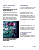
Benchmark MPA1 Instruction Manual 2-Channel Microphone Preamplifier
Safety Information Voltage Selection CAUTION: THE FUSE DRAWER INCLUDES A VOLTAGE SELECTION SWITCH WITH TWO SETTINGS: “110” AND “220”. CHECK TO SEE THAT IT IS PROPERLY CONFIGURED FOR YOUR LOCATION BEFORE CONNECTING AC POWER. Incorrect configuration may blow fuses or cause erratic operation. Repairs CAUTION: DO NOT SERVICE OR REPAIR THIS PRODUCT UNLESS PROPERLY QUALIFIED. ONLY A QUALIFIED TECHNICIAN SHOULD PERFORM REPAIRS.
Contents Safety Information 2 Voltage Selection Repairs Fuses Modifications 2 2 2 2 Contents 3 Overview 4 Features 5 Connections 6 Microphone Inputs (L and R) Balanced XLR Outputs Output Signal Levels Driving Unbalanced Loads AC Power Entry Connector Fuse Holder Preamp Section Preamp Overview Microphone Gain Controls Input Topology Two-Stage RF Filter and CMRR Phantom Power Switches Input Protection Polarity Switch 40 Hz High-Pass Filters LED Output Level Meters 6 6 7 7 7 7 8 8 8 8 8 9 9 9 9
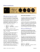
Overview The MPA1 is a 2-channel microphone preamplifier that is designed to achieve the highest performance available in a microphone preamplifier. The MPA1 is designed for maximum transparency, wide bandwidth, low-noise, low-distortion, and superior EMI immunity. It is well suited for the most demanding applications in studios and live venues. The MPA1 is the next evolution of Benchmark’s legendary microphone preamplifier systems.
Features • Two Transformerless Microphone Inputs • Two Balanced Direct Outputs (XLR) • Monolithic Low-Noise Transistor Quads on Each Microphone Input • Precision-Tuned, Two-Stage RF Filter on Each Microphone Input • Precision-Matched Resistor Gain Control Switches on Every Microphone Input • 2-dB per Switch Step; Maximum Gain - 74 dB; Maximum Gain - 0 dB (Unity) • ‘Virtual’ 38-position Gain Control Switch for Continuous Gain Control • Four Segment Gain Range Indicator • +27.
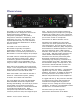
Connections Microphone Inputs (L and R) The balanced transformerless microphone inputs use locking Neutrik™ gold-pin female XLR jacks with both pin 1 (Ground) and the XLR shell directly bonded to the chassis. This direct bonding is important for maximum RF shielding and for immunity to hum due to shield currents. Each input includes Benchmark’s precision-tuned, two-stage RF filter for outstanding RF immunity.
Output Signal Levels AC Power Entry Connector The maximum output level on the balanced outputs is +27.5 dBu. Each channel’s output can be monitored with the four-segment LED output level meter. The AC power input uses a standard IEC type connector and includes a power switch. Factory-configured 110V units ship with a power cord. 220V units ship without a power cord. Location-specific IEC style power cords may be purchased from a local source (including any local Benchmark dealer).
Preamp Section Preamp Overview Input Topology Each preamp channel includes switches for phantom power, polarity, and 40 Hz highpass filter. Each channel also has a 38position gain control switch and a 4-segment output level meter. Inputs are fully protected against overloads and phantom power transients. The first gain stage on each microphone input is built around precision-matched, monolithic, low-noise transistor quads. Bandwidth is 500 kHz, IMD and THD are virtually non-existent.
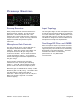
Phantom Power Switches Input Protection Up = Phantom On Down = Phantom Off Under certain circumstances, phantom power can cause large voltage transients. The MPA1 is equipped with high-speed, high-current, low-capacitance protection circuits that protect the sensitive input-transistors from the worst-case phantom-induced transients. CAUTION: ALWAYS TURN OFF PHANTOM POWER AND WAIT SEVERAL SECONDS BEFORE CONNECTING OR DISCONNECTING MICROPHONES. The MPA1 has an internal ‘Phantom Defeat’ jumper.
LED Output Level Meters Each preamp channel is equipped with a foursegment LED output level meter. The LED’s are driven by a peak detection and stretching circuit so that very short transients can be observed. The first green LED (-20 dBu) illuminates when the output signal has an amplitude of at least -20 dBu. The second green LED (+4 dBu) illuminates at an output level of at least +4 dBu. The yellow LED (+24 dBu) illuminates at an output level of at least +24 dBu.
HPA2™ Headphone Output The output of each channel’s preamp is directed to the headphone amplifier, Benchmark’s signature HPA2™ headphone amplifier. This high-current, high-output amplifier has an output impedance of 0Ohms. It is designed to drive loads as low as 30-Ohms without any increase in distortion. It also has sufficient amplitude to drive lowsensitivity 600-Ohm headphones.
Rack Mounting There are multiple solutions for rackmounting the MPA1. An optional RackMount Coupler allows the mounting of any two Benchmark System1™ products in a single rack space. A Blank Rack Panel can be added when only one unit is being racked. The System1™ Universal Rack Adapter is a tray solution. These rack-mount solutions are available from Benchmark. Call us, visit our website (http://www.BenchmarkMedia.com), or contact your dealer to purchase these accessories.
Performance Graphs Frequency Response Audio Precision PRE420 - Frequency Response 02/19/07 11:33:00 +3 +2.8 +2.6 +2.4 +2.2 +2 +1.8 +1.6 +1.4 +1.2 +1 +0.8 +0.6 +0.4 d B r +0.2 A -0.2 +0 -0.4 -0.6 -0.8 -1 -1.2 -1.4 -1.6 -1.8 -2 -2.2 -2.4 -2.6 -2.8 -3 10 20 50 100 200 500 1k 2k 5k 10k 20k 50k 100k 200k Hz Sweep Trace Color Line Style Thick Data Axis Comment 1 1 Red Solid 4 Anlr.
High-Pass Filter - Frequency Response Audio Precision PRE420 - Frequency Response 02/19/07 11:33:00 +3 +2.8 +2.6 +2.4 +2.2 +2 +1.8 +1.6 +1.4 +1.2 +1 +0.8 +0.6 +0.4 d B r +0.2 A -0.2 +0 -0.4 -0.6 -0.8 -1 -1.2 -1.4 -1.6 -1.8 -2 -2.2 -2.4 -2.6 -2.8 -3 10 20 50 100 200 500 1k 2k 5k 10k 20k 50k 100k 200k Hz Sweep Trace Color Line Style Thick Data Axis Comment 2 1 Red Solid 4 Anlr.Level A Left HP Filter On The above graph shows the response of the 40 Hz high-pass filter.
Inter-Channel Phase Response Audio Precision PRE420 - Inter-Channel Phase Response 02/19/07 11:35:37 +1 +0.9 +0.8 +0.7 +0.6 +0.5 +0.4 +0.3 +0.2 +0.1 d e g +0 -0.1 -0.2 -0.3 -0.4 -0.5 -0.6 -0.7 -0.8 -0.9 -1 10 20 50 100 200 500 1k 2k 5k 10k 20k 50k 100k Hz This graph shows that the differential phase is significantly better than ± 0.05 degrees from 10 Hz to 20 kHz.
THD+N vs. Frequency Measurement Bandwidth = 10Hz to 80 kHz, Gain = 30 to 60 dB, Output Level = +4 dBu Audio Precision PRE420 - THD+N vs Frequency at 60 dB Gain, BW=80 kHz 02/21/07 09:56:41 0.01 -80 -82 -84 0.005 -86 -88 -90 -92 0.002 -94 -96 -98 d B 0.001 % -100 -102 -104 0.0005 -106 -108 -110 -112 0.0002 -114 -116 -118 -120 20 50 100 200 500 1k 2k 5k 10k 20k 50k 80k 0.
Wideband THD+N vs. Frequency Measurement Bandwidth = 10 Hz to 500 kHz, Gain = 30 to 60 dB, Output Level = +4 dBu Audio Precision PRE420 - Wideband THD+N vs Frequency, BW=500 kHz 02/19/07 16:16:11 0.1 -60 -62 -64 0.05 -66 -68 -70 -72 0.02 -74 -76 -78 d B 0.01 -80 % -82 -84 0.005 -86 -88 -90 -92 0.002 -94 -96 -98 -100 20 50 100 200 500 1k 2k 5k 10k 20k 50k 100k 200k 0.
Equivalent Input Noise vs. Gain The above plot shows the Equivalent Input Noise (EIN) of the MPA1 as a function of gain. Measurement bandwidth is 20 Hz to 20 kHz. Input termination is 150 Ohms.
Noise Spectrum 32k B-H FFT, Gain = 60 dB, 0 dBr = 0 dBu at input Audio Precision Noise Spectrum, Gain = 60 dB, 0 dBr = 0 dBu at Input dx=120.996 Hz +0 02/19/07 11:27:19 dy=-3.948 dB -10 -20 -30 -40 -50 -60 -70 -80 d B r A -90 -100 -110 -120 -130 -140 -145.066 -150 -149.014 -160 -170 -180 -190 -200 10 59.6606 50 20 100 180.657 200 500 1k 2k 5k 10k 20k 30k Hz Sweep Trace Color Line Style Thick Data Axis 1 1 Red Solid 4 Fft.Ch.1 Ampl Left Comment Cursor1 Cursor2 *-145.
THD Spectrum at 1 KHz Audio Precision 1 kHz FFT at 60 dB Gain, Output Level = +24 dBu, 0 dBr = +24 dBu dx=1.00024 kHz -100 02/21/07 09:43:49 dy=-11.343 dB -100 -102 -102 -104 -104 -106 -106 -108 -108 -110 -110 -111.404 -112 -112 -114 -114 -116 -116 -118 -118 -120 -120 -122 d -122.747 -124 B r -126 A -128 -122 -130 -130 -132 -132 -134 -134 -136 -136 -138 -138 -140 -140 -142 -142 -144 -144 -146 -146 -148 -148 -124 d B r -126 A -128 -150 2.00513k 2k 3.
THD Spectrum at 10 KHz Audio Precision 10 kHz FFT at 60 dB Gain, Output Level = +24 dBu, 0 dBr = +24 dBu dx=10.0073 kHz -100 02/19/07 11:09:30 dy=-9.515 dB -102 -104 -106 -108 -109.271 -110 -112 -114 -116 -118 -118.787 -120 -122 d B r -124 -126 A -128 -130 -132 -134 -136 -138 -140 -142 -144 -146 -148 -150 2k 4k 6k 8k 10k 12k 14k 16k 18k 20.022k 20k 22k 24k 26k 28k 30.0293k 30k 32k Hz Sweep Trace Color Line Style Thick Data Axis 1 1 Red Solid 4 Fft.Ch.
Specifications Microphone Preamps Number of Preamps 2 Connectors Gold-Pin Neutrik™ female XLR with direct ground feature Grounding Direct bonding of pin 1 to chassis Input Impedance 8.1k Ohms Gain Range 0 dB to 74 dB Maximum Input Level @ Rated THD+N +27.5 dBu (+25.3dBV, 18.4 Vrms) Phantom Power +48V w/individual switches High-Pass (rumble filter) 40 Hz second-order 12-dB/octave RF Protection Dual-stage Preamp Bandwidth -0.02 dB at 10 Hz -0.
Direct Outputs Number of Outputs 2 Connectors Gold-Pin Neutrik™ male XLR with direct ground feature Output Impedance 60 Ohms Balanced 30 Ohms Unbalanced (pin 3 floating) Maximum Output Level at Rated Spec +27.5 dBu Drive capability at rated THD+N 300 Ohms Output Type Transformerless Voltage and Impedance Balanced HPA2™ Headphone Amplifier Number of Outputs 1 Connector ¼” TRS with switch contacts Output Impedance < 0.11 Ohms, 10 Hz to 200 kHz Maximum Output Level at 0.001% THD+N +23.
LED Output Meters and Gain Indicators Output Meters 4-LED Meter (per channel) Output Level Indicators +28 dBu (red) +24 dBu (orange) +4 dBu (green) -20 dBu (green) Gain Indicators “Max 74 dB” RED LED: Total Gain = +74 dB (Maximum preamp gain) “+48 dB” GREEN LED: Total Gain = Dial + 48 dB “+24 dB” GREEN LED: Total Gain = Dial + 24 dB NO LED: Total Gain = Dial + 0 dB “Min 0dB” RED LED: Total Gain = Unity Gain (Minimum preamp gain) AC Power Requirements Input Operating Voltage Range (VAC RMS) 120 V sett
Dimensions Form Factor ½ Rack Wide, 1 RU High Depth behind front panel 8.5” (216 mm) Overall depth including knobs and connectors but without power cord 9.33” (237 mm) Width excluding 19” rack ears 9.5” (249 mm) Height excluding removable feet 1.725” (44.5 mm) Weight MPA1 only 3.5 lb. MPA1 with power cord, extra fuses, and manual 4.5 lb. Shipping weight 7 lb.
Regulatory Compliance FCC Notice (U.S. Only) NOTICE: This equipment has been tested and found to comply with the limits for a Class B digital device, pursuant to Part 15 of the FCC Rules. These limits are designed to provide reasonable protection against harmful interference in a residential installation. This equipment generates, uses, and can radiate radio frequency energy and, if not installed and used in accordance with the instructions, may cause harmful interference to radio communications.
CE Certificate of Conformity MPA1 Instruction Manual Page 27
Warranty Information The Benchmark 1 Year Warranty Benchmark Media Systems, Inc. warrants its products to be free from defects in material and workmanship under normal use and service for a period of one (1) year from the date of delivery. This warranty extends only to the original purchaser. This warranty does not apply to fuses, lamps, batteries, or any products or parts that have been subjected to misuse, neglect, accident, modification, or abnormal operating conditions.
Benchmark Extended Warranty The Benchmark Extended 5* Year Warranty Benchmark Media Systems, Inc. optionally extends the standard one (1) year warranty to a period of five (5)* years from the date of delivery. *For the extended warranty to become effective, the original purchaser must register the product at the time of purchase either by way of the prepaid registration card or through the product registration section of the Benchmark Media Systems, Inc. website.
Calibration CAUTION: ROUTINE CALIBRATION SHOULD NOT BE REQUIRED. THE FOLLOWING PROCEDURE SHOULD ONLY BE USED BY A QUALIFIED TECHNICIAN. This procedure will restore the MPA1 to factory calibration if controls have been moved from factory settings. +48V Adjustment 1. Using a DC voltmeter, measure the voltage across D23 and adjust “+48V Adjust” (R107) until the meter reads 48V. Copyright © 2008 Benchmark Media Systems, Inc. All rights reserved. Benchmark Media Systems, Inc. 203 Hampton Place, Ste.