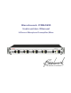
Benchmark PRE420 Instruction Manual 4-Channel Microphone Preamplifier/Mixer
Safety Information Voltage Selection CAUTION: THE FUSE DRAWER INCLUDES A VOLTAGE SELECTION SWITCH WITH TWO SETTINGS: “110” AND “220”. CHECK TO SEE THAT IT IS PROPERLY CONFIGURED FOR YOUR LOCATION BEFORE CONNECTING AC POWER. Incorrect configuration may blow fuses or cause erratic operation. Repairs CAUTION: DO NOT SERVICE OR REPAIR THIS PRODUCT UNLESS PROPERLY QUALIFIED. ONLY A QUALIFIED TECHNICIAN SHOULD PERFORM REPAIRS.
Contents Safety Information 2 Voltage Selection Repairs Fuses Modifications 2 2 2 2 Contents 3 Overview 4 Features 6 Connections 7 Microphone Inputs (1-4) Balanced Outputs – Overview Driving Unbalanced Loads Output Signal Levels Direct Outputs (1-4) Control Room Outputs (L&R) Main Outputs (L&R) AC Power Entry Connector Fuse Holder Preamp Section Preamp Overview Input Topology Microphone Gain Controls Blocking RF, EMI, and Noise Phantom Power Switches Input Protection MirrorPan™ Pan Controls 20
Overview The PRE420 is a 4-channel microphone preamplifier/mixer and is designed to achieve the highest performance available in a microphone preamplifier. The PRE420 is designed for maximum transparency, wide bandwidth, low-noise, low-distortion, and superior RF immunity. It is well suited for the most demanding applications in studios and live venues. The PRE420 is the next evolution of Benchmark’s legendary MPS-420 microphone preamplifier.
dimensional shield surrounding the microphone-level signal traces to block RF interference. Also, the microphone-level traces are arranged in a star-quad layout to prevent magnetic interference. Benchmark's innovative shielding and filtering techniques have given Benchmark microphone-preamps a proven track record for exceptional performance in difficult, RF-intensive locations.
Features • • • • • • • • • • • • • • • • • • • • • • • • • • • • • • • • Four Transformerless Microphone Inputs Four Balanced Direct Outputs (XLR) Balanced Left and Right Main Outputs (XLR) Balanced Left and Right Control Room Outputs (XLR) HPA2™ “0-Ohm” 1/4” TRS Headphone Output Precision-Matched Monolithic Low-Noise Transistor Quads on Each Microphone Input High-Current High-Speed Low-Capacitance Phantom Protection Circuits Fully Protected Against Phantom Hot-Plug and Cable-Shorting Scenarios Balanced Tr
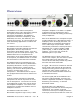
Connections Microphone Inputs (1-4) The balanced transformerless microphone inputs use locking Neutrik™ gold-pin female XLR jacks with both pin 1 (Ground) and the XLR shell directly bonded to the chassis. This direct bonding is important for maximum RF shielding and for immunity to hum due to shield currents. • • • • XLR pin 2 = + Audio In XLR pin 3 = - Audio In XLR pin 1 = Cable Shield – bonded to chassis XLR shell – bonded to chassis The microphone inputs have a wide operating range.
pin Neutrik™ male XLR connectors with direct chassis bonding of both pin 1 and the connector shell. This direct bonding is important for maximum RF shielding and for immunity to hum due to shield currents. All outputs are transformerless and have an impedance of 60 Ohms balanced or 30 Ohms unbalanced. All outputs are equipped with high-performance drivers that can drive high signal levels into load impedances as low as 300 Ohms without an increase in distortion.
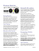
Preamp Section Blocking RF, EMI, and Noise The entire signal path of the PRE420 has a generously wide bandwidth: 500 kHz. This creates a significant demand for exceptional RF filtering and shielding – a demand Benchmark fulfills. Preamp Overview Each preamp channel includes switches for phantom power, a 20 dB pad, and a 40 Hz high-pass filter. Each channel also has a center-detent MirrorPan™ control, a 41detent gain control, a Phantom warning LED, and a 2-segment output level meter.
current low-capacitance input protection circuits that protect the sensitive low-noise input transistors from the worst-case phantom-induced transients. Large transients are produced when a microphone is connected or disconnected while phantom power is on. The worst possible transients occur when a microphone cable has an intermittent short to ground from either pin 2 or pin 3. The PRE420 is very well protected against both of the above.
MirrorPan™ Pan Controls The PRE420 incorporates Benchmark’s new MirrorPan™ constant-power pan control. The advantages of MirrorPan™ include: • • • • • Accurate 3-dB constant-power pan law Accurate balance at center detent Excellent channel separation when fully panned Ultra-low distortion Ultra-low noise Benchmark’s MirrorPan circuit eliminates the distortion and pan-law errors caused by panpot wiper current.
Stereo/Mono Solo Switch Microphones may be monitored before the pan control (mono) or after the pan control (stereo). Press the “Mono/Stereo” switch for stereo solo. Stereo monitoring can be used to check the pan position of a single microphone or any combination of microphones.
Control Room Monitor Fader Outputs The output of the solo bus is directed to the “monitor” fader and then to the headphone and “control room” outputs. Maximum output level is 29.5 dBu. All drivers are high-current low-distortion amplifiers. These are capable of driving loads as low as 300 Ohms without an increase in distortion. The “monitor” fader is located to the right of the solo buttons. It controls the output level of the headphone jack and the balanced control room outputs.
HPA2™ Headphone Output The output of the solo bus is directed to the “monitor” fader and then to the headphone and “control room” outputs. The headphone output is driven by Benchmark’s signature HPA2™ headphone amplifier. This high-current, high-output amplifier has an output impedance of 0Ohms. It is designed to drive loads as low as 30-Ohms without any increase in distortion. It also has sufficient amplitude to drive lowsensitivity 600-Ohm headphones. impedance decreases.
Mix Outputs Main Fader The output of the mix bus is directed to the “Main” fader and then to the “Main” outputs. The “main” fader is located at the far right of the front panel. This stereo fader has factory adjusted balance trim circuitry to provide accurate L/R balance. Maximum output level is 29.5 dBu. All drivers are high-current low-distortion amplifiers. These are capable of driving loads as low as 300 Ohms without an increase in distortion.
Rack Mounting To enable rack mounting, the front panel of the PRE420 has rack-mount holes that are machined to conform to standard rack mount dimensions. The PRE420 ships with rubber feet that should be removed whenever another device will be mounted directly below the PRE420. Mounting Near Other Equipment CAUTION: STRAY MAGNETIC FIELDS FROM ADJACENT EQUIPMENT MAY CAUSE MAGNETICALLY INDUCED HUM IN THE SENSITIVE HIGH-GAIN PREAMP CIRCUITS.
Performance Graphs Frequency Response Audio Precision PRE420 - Frequency Response 02/19/07 11:33:00 +3 +2.8 +2.6 +2.4 +2.2 +2 +1.8 +1.6 +1.4 +1.2 +1 +0.8 +0.6 +0.4 d B r +0.2 A -0.2 +0 -0.4 -0.6 -0.8 -1 -1.2 -1.4 -1.6 -1.8 -2 -2.2 -2.4 -2.6 -2.8 -3 10 20 50 100 200 500 1k 2k 5k 10k 20k 50k 100k 200k Hz Sweep Trace Color Line Style Thick Data Axis Comment 1 1 Red Solid 4 Anlr.
High-Pass Filter - Frequency Response Audio Precision PRE420 - Frequency Response 02/19/07 11:33:00 +3 +2.8 +2.6 +2.4 +2.2 +2 +1.8 +1.6 +1.4 +1.2 +1 +0.8 +0.6 +0.4 d B r +0.2 A -0.2 +0 -0.4 -0.6 -0.8 -1 -1.2 -1.4 -1.6 -1.8 -2 -2.2 -2.4 -2.6 -2.8 -3 10 20 50 100 200 500 1k 2k 5k 10k 20k 50k 100k 200k Hz Sweep Trace Color Line Style Thick Data Axis Comment 2 1 Red Solid 4 Anlr.Level A Left HP Filter On The above graph shows the response of the 40 Hz high-pass filter.
Inter-Channel Phase Response Audio Precision PRE420 - Inter-Channel Phase Response 02/19/07 11:35:37 +1 +0.9 +0.8 +0.7 +0.6 +0.5 +0.4 +0.3 +0.2 +0.1 d e g +0 -0.1 -0.2 -0.3 -0.4 -0.5 -0.6 -0.7 -0.8 -0.9 -1 10 20 50 100 200 500 1k 2k 5k 10k 20k 50k 100k Hz This graph shows that the differential phase is significantly better than ± 0.05 degrees from 10 Hz to 20 kHz. PRE420 Instruction Manual – rev.
THD+N vs. Frequency Measurement Bandwidth = 10Hz to 80 kHz, Gain = 30 to 60 dB, Output Level = +4 dBu Audio Precision PRE420 - THD+N vs Frequency at 60 dB Gain, BW=80 kHz 02/21/07 09:56:41 0.01 -80 -82 -84 0.005 -86 -88 -90 -92 0.002 -94 -96 -98 d B 0.001 % -100 -102 -104 0.0005 -106 -108 -110 -112 0.0002 -114 -116 -118 -120 20 50 100 200 500 1k 2k 5k 10k 20k 50k 80k 0.
Wideband THD+N vs. Frequency Measurement Bandwidth = 10 Hz to 500 kHz, Gain = 30 to 60 dB, Output Level = +4 dBu Audio Precision PRE420 - Wideband THD+N vs Frequency, BW=500 kHz 02/19/07 16:16:11 0.1 -60 -62 -64 0.05 -66 -68 -70 -72 0.02 -74 -76 -78 d B 0.01 -80 % -82 -84 0.005 -86 -88 -90 -92 0.002 -94 -96 -98 -100 20 50 100 200 500 1k 2k 5k 10k 20k 50k 100k 200k 0.
Equivalent Input Noise vs. Gain The above plot shows the Equivalent Input Noise (EIN) of the PRE420 as a function of gain. Measurement bandwidth is 20 Hz to 20 kHz. Input termination is 150 Ohms. PRE420 Instruction Manual – rev.
Noise Spectrum 32k B-H FFT, Gain = 60 dB, 0 dBr = 0 dBu at input Audio Precision Noise Spectrum, Gain = 60 dB, 0 dBr = 0 dBu at Input dx=120.996 Hz +0 02/19/07 11:27:19 dy=-3.948 dB -10 -20 -30 -40 -50 -60 -70 -80 d B r A -90 -100 -110 -120 -130 -140 -145.066 -150 -149.014 -160 -170 -180 -190 -200 10 59.6606 50 20 100 180.657 200 500 1k 2k 5k 10k 20k 30k Hz Sweep Trace Color Line Style Thick Data Axis 1 1 Red Solid 4 Fft.Ch.1 Ampl Left Comment Cursor1 Cursor2 *-145.
THD Spectrum at 1 KHz Audio Precision 1 kHz FFT at 60 dB Gain, Output Level = +24 dBu, 0 dBr = +24 dBu dx=1.00024 kHz -100 02/21/07 09:43:49 dy=-11.343 dB -100 -102 -102 -104 -104 -106 -106 -108 -108 -110 -110 -111.404 -112 -112 -114 -114 -116 -116 -118 -118 -120 -120 -122 d -122.747 -124 B r -126 A -128 -122 -130 -130 -132 -132 -134 -134 -136 -136 -138 -138 -140 -140 -142 -142 -144 -144 -146 -146 -148 -148 -124 d B r -126 A -128 -150 2.00513k 2k 3.
THD Spectrum at 10 KHz Audio Precision 10 kHz FFT at 60 dB Gain, Output Level = +24 dBu, 0 dBr = +24 dBu dx=10.0073 kHz -100 02/19/07 11:09:30 dy=-9.515 dB -102 -104 -106 -108 -109.271 -110 -112 -114 -116 -118 -118.787 -120 -122 d B r -124 -126 A -128 -130 -132 -134 -136 -138 -140 -142 -144 -146 -148 -150 2k 4k 6k 8k 10k 12k 14k 16k 18k 20.022k 20k 22k 24k 26k 28k 30.0293k 30k 32k Hz Sweep Trace Color Line Style Thick Data Axis 1 1 Red Solid 4 Fft.Ch.
Specifications Microphone Preamps Number of Preamps 4 Connectors Gold-Pin Neutrik™ female XLR with direct ground feature Grounding Direct bonding of pin 1 to chassis Input Impedance (pad off) 8.1k Ohms Input Impedance (pad on) 1.37k Ohms Gain Range (with pad off) 22 dB to 60 dB (to direct outputs) Gain Range (with pad on) 2 dB to 40 dB (to direct outputs) Maximum Input Level (pad off) +7 dBu (+4.8 dBV, 1.7 Vrms) Maximum Input Level (pad on) +27 dBu (+24.8 dBV, 17.
Direct Outputs Number of Outputs 4 Connectors Gold-Pin Neutrik™ male XLR with direct ground feature Output Impedance 60 Ohms Balanced 30 Ohms Unbalanced (pin 3 floating) Maximum Output Level without clipping +29.
MirrorPan™ Constant-Power Pan Circuit Number of pan controls 4 Pan Law 3-dB (constant power to stereo out) Deviation from Constant Power +/- 0.25 dB Channel Separation when Fully Panned > 71 dB Balance at Center Detent +/- 0.25 dB THD+N Better than -112 dB, 0.00024% HPA2™ Headphone Amplifier Number of Outputs 1 Connector ¼” TRS with switch contacts Output Impedance < 0.11 Ohms, 10 Hz to 200 kHz Maximum Output Level at 0.001% THD+N +23.5 dBu into 600 Ohms (0.24 W) +19.
LED Status Indicators and Meters +48V Phantom Indicators 4 Solo Warning Indicator 1 Power Indicator 1 Blue Meter Indicators 6 Dual LED Meters Meter Locations 4 – microphone inputs 2 – main outputs Meter Specifications Green LED – intensity modulated signal presence, threshold = -8 dBu, full brightness at +24 dBu Red LED – threshold = +24 dBu adjustable, includes peak-responding pulse stretch circuit for viewing fast transients AC Power Requirements Input Operating Voltage Range (VAC RMS) 120 V
Dimensions Form Factor 19” Rack Mount, 1 RU High Depth behind front panel 11.75” (298.5 mm) Overall depth including knobs and connectors but without power cord 12.625” (321 mm) Width excluding 19” rack ears 17.5” (445 mm) Height excluding removable feet 1.725” (43.8 mm) Weight PRE420 only 8.05 lb. (3.65 kg) PRE420 with power cord, extra fuses, and manual 9 lb. (4.1 kg) Shipping weight 11 lb. (5 kg) PRE420 Instruction Manual – rev.
Regulatory Compliance FCC Notice (U.S. Only) NOTICE: This equipment has been tested and found to comply with the limits for a Class B digital device, pursuant to Part 15 of the FCC Rules. These limits are designed to provide FCC Notice reasonable protection against harmful interference in a residential installation. This equipment generates, uses, and can radiate radio frequency energy and, if not installed and used in accordance with the instructions, may cause harmful interference to radio communications.
CE Certificate of Conformity PRE420 Instruction Manual – rev.
Warranty Information The Benchmark 1 Year Warranty Benchmark Media Systems, Inc. warrants its products to be free from defects in material and workmanship under normal use and service for a period of one (1) year from the date of delivery. This warranty extends only to the original purchaser. This warranty does not apply to fuses, lamps, batteries, or any products or parts that have been subjected to misuse, neglect, accident, modification, or abnormal operating conditions.
Benchmark Extended Warranty The Benchmark Extended 5* Year Warranty Benchmark Media Systems, Inc. optionally extends the standard one (1) year warranty to a period of five (5)* years from the date of delivery. *For the extended warranty to become effective, the original purchaser must register the product at the time of purchase either by way of the prepaid registration card or through the product registration section of the Benchmark Media Systems, Inc. website.
Calibration 7. Connect audio level meter to channel 1 direct output. CAUTION: ROUTINE CALIBRATION SHOULD NOT BE REQUIRED. THE FOLLOWING PROCEDURE SHOULD ONLY BE USED BY A QUALIFIED TECHNICIAN. 8. Adjust channel 1 “Max Gain Lim” (R53) until output level is +24 dBu at channel 1 direct output. This procedure will restore the PRE420 to factory calibration if controls have been moved from factory settings.
21. Set audio tone generator to 1 kHz with an output level of -36 dBu (or level used in step 3). 35. Set audio tone generator to 1 kHz with an output level of -36 dBu (or level used in step 3). 22. Connect tone generator to microphone 1 input. 36. Connect tone generator to microphone 1 input. 23. Connect audio level meters to “Control Room” L & R outputs. 37. Connect audio level meters to “Main” L & R outputs. 24. Adjust Channel 1 “Pan Bal” (R27) until the “Control Room” L & R outputs are balanced.
Copyright © 2007 Benchmark Media Systems, Inc. All rights reserved. Benchmark Media Systems, Inc. 203 Hampton Place, Ste. 2 Syracuse, NY 13206 USA +1-315-437-6300, FAX +1-315-437-8119 www.benchmarkmedia.com PRE420 Instruction Manual – rev.