
Specifications

Page 27
mCHP
BOILERMATE
A-CLASS
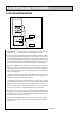
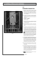
Figure 5.1 Appliance wiring terminals NO
clock option
Note: Details of wiring terminals with
programmer fitted as standard are shown in
figure 3.6
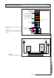
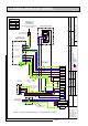
Figure 5.2
Schematic Electrical Wiring Diagram
PN
PE
PL
SL_E
SL_B
SL_O
SL_R
SL_W
SL_H
PE
PE
PE
L
L
N
N
N
N
E
N
MCB2 16A
MCB2 16A
MCB3 6A
Appliance Internal Wiring
See figure 3.6
Pump supply
Neutral (N) 230V
Permanent Live (L) 230V
From mCHP
230V ac
(2) mCHP_boost ‘switched’ live (L)
(3) Electric boost on signal (L)
(1) mCHP_on/off ‘switched’ live (L)
Room stat ‘switched’ live (L)
Programmer HW ‘switched’ live (L)
Programmer CH ‘switched’ live (L)
N
L
E
Mains supply
230V, 50Hz, 32A
6mm
2
(4)
230V, 50Hz
Supply
2 Pole, 32A Isolator 2 Pole, 6A Isolator
230V, 50Hz
mCHP
Appliance
mCHP
BoilerMate
Room
thermostat
230V, 50Hz
32A, Supply
mCHP on-off signal (230V, 50Hz)
mCHP electric boost signal
mCHP boost mode signal (230V, 50Hz)
mCHP pump on-off supply (230V, 50Hz)
(1)
(2)
(3)
(4)
INSTALLATION AND WIRING 5.0