
Specifications

Page 20
3.0 TECHNICAL SPECIFICATION
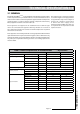
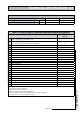
Table 3.6 mCHP BoilerMate
A-CLASS
Indentification Values
Models ID Resistor Value Controller Code
mCHP BMA 225
10K A06
mCHP BMA 235
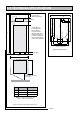
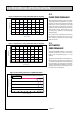
Table 3.7 sensor used in mCHP BoilerMate
Display Sensor Connector J9 pins Location
S1 T Overheat 1 6 & 14
Top of store in dry pocket (S1 & S2 are in single housing)
S2 T Overheat 2 2 & 10
S3 T DHW in 3 & 11 In cold water inlet pipe (Wet i.e. direct)
S4 T DHW out 4 & 12 In hot water outlet pipe (Wet i.e. direct)
S5 T Tank bottom 5 & 13 Bottom of store in dry pocket for Off-Peak IH
S6 T Tank middle 1 & 9 Middle of store in dry pocket for On-Peak IH
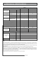
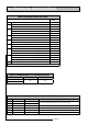
Table 3.5 System Control Set Points
BMA 225
BMA 235
1 DHW control temperature, sensor S4 55ºC
2 Hot water priority ON set point, Sensor S6 54ºC
Hot water priority OFF set point, Sensor S6 58ºC
3
(1)
CH Pump max speed 255
CH Pump min speed 110
CH return temperature set point, Sensor S5 55ºC
4 Bottom store sensor, S5, ON set point 60ºC
Bottom store sensor, S5, OFF set point 70ºC
5 Middle store sensor, S6, ON set point 68ºC
Middle store sensor, S6, OFF set point 77ºC
6 mCHP boost ON set point in HW only mode (T_HW_boost_on) 52ºC
mCHP boost OFF set point in HW only mode (T_HW_boost_off) 57ºC
7 mCHP boost ON set point in CH only mode (T_CH_boost1_on) 55ºC
mCHP boost OFF set point in CH only mode (T_CH_boost1_off) 65ºC
mCHP boost ON/OFF rate of change set point (R_CH_boost1)
8 Electric boost ON set point in CH only mode (T_CH_boost2_on) 40ºC
Electric boost OFF set point in CH only mode (T_CH_boost2_off) 50ºC
Electric boost ON/OFF rate of change set point (R_CH_boost2)
9 Overheat set point, Sensor S1/S2 95ºC
Notes:
(1)
Only when modulating pump option is specified