A-CLASS mCHP BoilerMate DESIGN, INSTALLATION AND SERVICING INSTRUCTIONS Model Numbers mCHP BMA 225 mCHP BMA 235 benchmark TM A CENTRAL HEATING AND MAINS PRESSURE HOT WATER APPLIANCE INCORPORATING A THERMAL STORE - FOR USE WITH mCHP UNITS IN DOMESTIC DWELLINGS ALL MODELS COMPLY WITH THE WATER HEATER MANUFACTURERS SPECIFICATION FOR INTEGRATED THERMAL STORES iSSUE 4: 06-08 The code of practice for the installation, commissioning & servicing of central heating systems
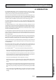
iSSUE 4: 06-08 Models These appliances have been certified for safety and are WRAS approved and listed and are designed to be used with mCHP appliances in domestic dwellings. Therefore it is important these instructions are followed and used in conjunction with mCHP appliance manufacturer’s instructions.The appliance and the installation specifications must not be modified unless recommended and approved by Gledhill Water Storage Limited. SAFETY 1.
CONTENTS IMPORTANT NOTICES 2.0 SYSTEM DESCRIPTION 2.1 INTRODUCTION 2.2 OPERATION 2.2.1 Domestic Hot Water 2.2.2 Space Heating 2.2.3 Store Heating - Not Active 2.2.4 Store Heating - Active 2.2.5 Electric Backup 4 6 6 8 8 8 9 9 2.3 USER CONTROLS 11 2.3.1 2.3.2 2.3.3 2.3.4 On - Off Switch Push button Functions Red Lamp (LED) Functions CH and HW Programmer 11 11 11 11 3.0 TECHNICAL SPECIFICATION 12 3.1 3.2 3.3 3.4 3.5 3.6 3.6.1 3.6.2 3.6.3 3.6.4 3.
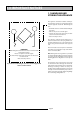
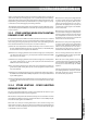
1.0 IMPORTANT NOTICES 1.1 HANDLING AND STORING THE APPLIANCE This appliance should be handled carefully to avoid damage and the recommended method is shown opposite. A team lift - When lifting the unit:• Work with someone of similar build and height if possible. • Choose one person to call the signal • Lift from the hips at the same time, and then raise the unit to the desired level. • Move smoothly in unison. The appliance supplied shrink wrapped on a timber installation base.
IMPORTANCE NOTICES 1.0 1.2 SYSTEM INSTALLATION Any installation must be in accordance with the relevant requirements of the current issue of Gas Safety (Installation and Use) Regulations, Local Building Regulations, Local Water Company Bylaws and Health & Safety Document No. 635 – The Electricity at Work Regulations 1989. The detailed recommendations are contained in the current issue of the following British Standards and Codes of Practices: BS 5440 Pts.
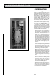
2.0 SYSTEM DESCRIPTION 2.1 INTRODUCTION The mCHP BoilerMateA-CLASS appliance shown in figure 2.1 is designed to provide improved space heating and mains pressure hot water and better electric and heat energy management when coupled to a domestic Micro Combined Heat and Power (mCHP) appliance. Any automatic mCHP unit designed to operate at flow temperature between 75oC and 85oC can be linked to the mCHP BoilerMateA-CLASS.
SYSTEM DESCRIPTION 2.0 2.1 iNTRODUCTION The mCHP BoilerMate A-Class shown schematically in figures 2.1 and 2.2 is primarily designed for the new build market. The thermal store completely isolates the mCHP unit from the space heating and hot water demands and functions. The heat losses from thermal stores should not be directly compared with heat losses from unvented or vented cylinders because they are treated differently in SAP.
2.0 SYSTEM DESCRIPTION The mCHP BoilerMate A-CLASS appliance user controls are shown in figure 2.5. All models are fitted with a single channel clock for programming heating ‘on’ times. All models can be supplied without this clock for use with a remote 2 channel programmer or programmable room thermostat etc. These should be supplied and specified by the installer. F & E cistern S1/S2 Thermal Store 2.2.
SYSTEM DESCRIPTION 2.0 If the store temperature falls below the pre-set limit (see table 3.5), the controller will either switch off the space heating pump or run it at minimum speed if modulating pump is fitted. The normal space heating pump operation will resume when the store temperature is greater than this pre-set limit. This is to provide a degree or priority to domestic hot water during high space heating demands. The modulating central heating pump can be specified as an option.
2.0 SYSTEM DESCRIPTION 2.2.5 ‘ SWITCH’ ELECTRIC BACK UP FACILITY The mCHP_BoilerMateA-CLASS is fitted with an electric backup facility. If the mCHP unit does not supply heat when requested and fails to heat the store, the user has the option of selecting the electric backup system until the mCHP appliance operation is restored.
SYSTEM DESCRIPTION 2.0 2.3 USER CONTROLS 2.3.4‘SWITCH’ OPERATION The front panel controls are shown in figure 2.5 below. By moving the mode rocker on the front panel from ‘normal’ to ‘switch’ position the electric backup boiler (switch) can be used as an alternative heat source for hot water and central heating, should there be a failure of the mCHP boiler. (See 2.2.7 Electric Backup Facility for further details) 2.3.
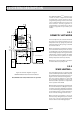
3.0 TECHNICAL SPECIFICATION 350mm Min access to comply with 'Water Regulations' CF OV 15 150 210 22 DHW 550 HR CF HF mCHP-Flow mCHP-R 560 510 22 *2 F&E cisterns are provided with the 235 model. To accommodate these the width of the cupboard will have to increase to 800mm or the cisterns will need to be located elsewhere A 50 70 300mm 475 F & E* Cistern 530 22 22 22 65 170 220 22 65 185 220 All dimensions in mm Figure 3.
TECHNICAL SPECIFICATION 3.0 3.1 GENERAL The mCHP_BoilerMateA-CLASS is only suitable for sealed heating systems and the technical specification is presented in tables 3.1 and 3.2. The model selection data is shown in table 3.3. The factory fitted or supplied standard components (shown in figures 2.1 and 2.2) and the optional components either factory fitted, supplied or available are listed in table 3.4.
3.0 TECHNICAL SPECIFICATION Table 3.
TECHNICAL SPECIFICATION 3.0 Table 3.3 Model Selection Guide BMA225 Maximum design heat loss of the dwelling (kW) Maximum number of bathrooms/En-suite shower rooms BMA235 6.0 8.0 1/1 2/1 Table 3.
3.0 TECHNICAL SPECIFICATION Figure 3.3 Performance range of Grundfos UPS 15-50 pump 6 The performance of Grundfos UPS 15-50 and UPS 15-60 pumps fitted in the appliances are shown in figures 3.3 and 3.4 respectively. The maximum performance of the modulating pumps (UPR range) is the same as the UPS range set at speed 3. As these pumps modulate their performance characteristics change downwards the same as setting lower speeds for non-modulating standard pumps. Pump head (m) 5 4 3 2 1 0 0 0.5 1 1.
mCHP N E Bl SL_E Electric_boost ON signal (SL) PL 3 Wh 9 L ML G/Y Br 7 Bl Br N 4 Bl Bl B 8 6 2 5 1 Br R Br BOILERMATE A-CLASS APPROVED DATE : JUNE 2006 L Or 10K Resistor B Or Wh B Br B R B SL_B mCHP_boost S/W Live (L) Wh ID_RESISTOR SL_N mCHP_On/Off S/W Live (L) R B WHITE GREEN / YELLOW Wh G/Y Bl YELLOW R Br Bl mCHP Modulating Pump Bl A2 14 R1 A1 13 Store Middle S6 SL_W HW Switched Live Y Store Bottom S5 PE ORANGE SL_H HTG Switched Live Or
3.0 TECHNICAL SPECIFICATION 3.
TECHNICAL SPECIFICATION 3.0 checking and setting the appliance code on the controller is described below. • The appliance selection menu (A0 ... A9) on the controller is hidden. It is only possible to get to the appliance selection using the reset button (Left hand, B1) on the main board. • When going from the show ‘ locking error’ to show ‘blocking error’ menu (see figure 3.10), do not release the button but hold it for 10 seconds. The display will change from ‘c’ to ‘A’.
3.0 TECHNICAL SPECIFICATION Table 3.
TECHNICAL SPECIFICATION 3.0 Table 3.8 Sensor Sensor control set point readings Display Sensor S1 Top/middle store sensor, S6, ON set point S2 Top/middle store sensor, S6, OFF set point S3 DHW Inlet sensor, S3, set point S4 DHW Outlet sensor, S4, set point S5 Bottom store sensor, S5, ON set point S6 Bottom store sensor, S5, OFF set point Table 3.
4.0 heating and hot water 4.1 HEATING AND HOT WATER SYSTEM DESIGN (a) All recommendations with regard to pipe work systems in this manual are generally based on the use of BS/EN Standard copper pipework and fittings. (b) However the plastic pipework system can be used in place of copper internally as long as the chosen system is recommended by the manufacturer for use in cold and hot water systems and is fully designed and installed in accordance with their recommendations.
heating and hot water 4.0 4.1.2 USE IN HARD WATER AREAS (a) The control system prevents the domestic water from exceeding 55oC for most of the operational time of the appliance and therefore limits the formation of scale . 4.1.3 COLD AND HOT WATER DISTRIBUTION NETWORK (a) As a minimum, it is recommended that the cold supply to the appliance internally is run in 22mm copper or equivalent in plastic and then from the appliance in 22mm past the hot water draw-off to the bath .
4.0 heating and hot water 4.2 SPACE HEATING DESIGN Thermal Store P2 Standard Sealed heating expansion kit to be supplied and fitted by installer. 1 bar CH rtn CH flow rab 1 Cold Raising Main Approved Filling Loop Space heating circuit PRV 3 Bar Figure 4.2 Schematic diagram of the sealed heating system (a) mCHP BoilerMateA-CLASS is only available for sealed heating systems and the schematic arrangement of a sealed heating system is shown in figures 2.3 and 4.2.
heating and hot water 4.0 To meet the requirements of Building Regulations for a boiler interlock it is recommended that the radiator in the area where the room thermostat is installed should be fitted with lock shield valves on both connections. (f) Plastic pipework: All the recommendations with regard to pipework systems in this manual are generally based on use of BS/EN Standard copper pipework and fittings.
5.0 installation and wiring 5.1 SITE REQUIREMENTS (a) The appliance is designed to be installed in an airing/cylinder cupboard on the 100mm high plinth supplied with the appliance and the minimum relevant dimensions are provided in section 3. The minimum dimensions shown in figure 3.2 and Table 3.1, allow for the passage/connection of pipes to the appliance from any direction as long as the appliance is installed on the base provided.
installation and wiring 5.0 (4) PE PN PL Pump supply From mCHP 230V ac (3) Electric boost on signal (L) (2) mCHP_boost ‘switched’ live (L) (1) mCHP_on/off ‘switched’ live (L) Room stat ‘switched’ live (L) Programmer HW ‘switched’ live (L) Programmer CH ‘switched’ live (L) Permanent Live (L) 230V Neutral (N) 230V Note: Details of wiring terminals with programmer fitted as standard are shown in figure 3.6 Mains supply N 230V, 50Hz, 32A L 6mm2 E Appliance Internal Wiring See figure 3.
5.0 installation and wiring 5.3 PIPEWORK CONNECTION (a) The position of the pipework connections is shown opposite in figure 5.3 the connection sizes and dimensions are shown in figure3.2 and Table 3.1. All connections are also labelled on the appliance. It is essential that the pipework is connected to the correct connection. (b) If using pushfit connections with the flexible hose kits, it is important to check that they are compatible.
installation and wiring 5.0 5.4 Electrical Wiring The appliance circuit diagram is shown in figure 3.6 and the external wiring terminal details are shown in figures 5.4 and 5.5. All external controls and equipment must be wired to these terminals. The mCHP unit manufacturers wiring instructions should be read in conjunction with this manual before commencing the wiring process. 5.4.1 GENERAL (a) This appliance MUST BE EARTHED. The wiring must comply with the current I.E.
5.0 installation and wiring B 3 Bl 2 Br 1 0.75mm² - 1.00mm² 3 core & E cable (230V, 50Hz) G/Y G/Y B Br Gry PE PN PL SL_E Br SL_B B SL_O Gry SL_R SL_W 0.75mm² - 1.0mm² 3 core & E + 2 core & E cable Room Thermostat Wh SL_H G/Y G/Y PE Gry SL Br L N PE PE PE 0.75mm² - 1.0mm² 3 core & E cable (230V, 50Hz) L Br Bl B B L N N Boiler mCHP prog 1A.FC7 DRG. NAME APPROVED A4 DRG.
installation and wiring 5.0 PE SL_B B SL_O Gry G/Y SL_R Gry Room Thermostat SL_W B SL_H G/Y PE G/Y Gry SL Br L N PE G/Y PE PE 0.75mm² - 1.0mm² 3 core & E cable (230V, 50Hz) Br L Br L Bl B N N B Mains supply 230V, 50Hz, 32A (6mm² - 10mm²) Br Br G/Y Local 2 pole isolator within 2m of Boilermate 6.0mm² Flat twin & earth Boilermate cable Boiler mCHP remote prog 1A.FC7 DRG. NAME A4 DRG.
6.0 commissioning 6.0 COMMISSIONING (a) It is essential that the system functions properly for optimum performance. To achieve this, the heating and the hot water system should be commissioned in accordance with the good practice and generally with the requirements of BS 6798, BS 5449 and BS 7593. Full details of the requirements are given in PAS 33:1999 under section 10 Commissioning.
commissioning 6.0 6.3 COMMISSIONING mCHP UNIT & BOILERMATE (b) Set heating clock to continuous and ensure that the room thermostat is calling for heat. This will be indicated by display segments V1.3 and V1.4 being on respectiveley. The BoilerMate controller will now:- (a) Check that the mCHP BoilerMate front panel switch is in ‘On’ position and the mode switch is in the ‘normal’ position. (b) The mCHP unit will not start i.
6.0 commissioning 6.5 COMMISSIONING DOMESTIC HOT WATER SYSTEM (a) When the store is hot, open a hot water tap nearest to the appliance at approximately 6 litres/minute. After about 2 – 3 seconds, the plate heat exchanger pump will start. This is indicated by on main PCB display by display segment H2.1 (see figure 6.2). (b) Record the hot water outlet temperature in the ‘Benchmark’ logbook.
SERVICING 7.0 Table 7.
APPENDIX A WATER SAVINGS Water related costs can be reduced by good plumbing practice. TAPS & MIXERS 1 1 2 1 2 TAP HALF OPEN Unregulated OVER 20 L/M Fitted with regulator 5, 6 OR 8 L/M 2 2 SHOWERS 4 FIXING OPTIONS FOR TAPS & MIXERS Unregulated 25 - 30 l/m Regulated 10 - 12 l/m Vast quantities of water are needlessly run off to waste due to Taps, Mixers and Showers discharging flow rates far in excess of the rates required for them to perform their duties.
APPENDIX B MANIFOLDS Manifold type: 1 - Stock Code MIP 050 (one bathroom, one en suite shower room, one cloakroom, one kitchen) Flow regulator (litres/minutes) Terminal fitting Hot water manifold outlets Quantity Cold water manifold outlets Quantity 18 Bath tap 1 1 9 Hand basin 3 3 12 Kitchen sink 1 1 9 Toilet cistern None 3 9 Shower 1 1 12 Washing machine 1 1 9 Dishwasher None 1 Total 7 11 Two sets of manifolds are available as an optional extra.
APPENDIX B The pressure loss through a flow regulator at the designated flow rate is about 1.8 bar. Therefore for the flow regulator to control the flow rate at pre-set level, the inlet pressure must be greater than 1.8 bar. If the inlet pressure is lower, the flow rate will be correspondingly less than the pre-set values. The maximum equivalent pipe lengths from the manifold to the terminal fittings can be estimated from the above information and the resistance characteristics of the pipes.
APPENDIX B The size of the distribution pipes supplying the manifold should be calculated using the method set out in BS 6700. A typical diagrammatic arrangement of a system using Manifold Type 1 is shown below. This is only meant to show the principles involved and the actual connection of fittings to the manifold will need to suit the arrangements shown on page 35.
APPENDIX C G U I D A N C E 2 N O T E S Inhibitor (Corrosion & scale protection of primary heating circuit) On filling the heating system and before the boiler is fired up, it is important to ensure the system water is treated with a suitable corrosion inhibitor, in accordance with the boiler manufacturer’s instructions.
APPENDIX D MANUAL HANDLING OF APPLIANCE PRODUCTS Description Manual handling means any transporting or supporting of a load (including lifting, putting down, pushing, pulling, carrying or moving) by hand or bodily force. Scope This assessment will cover the largest Appliance, namely ElectraMate, GulfStream, BoilerMate, SysteMate, PulsaCoil, Accolade and Stainless Lite manufactured by Gledhill. The maximum weight of the largest product in each range is 98kg and the size is 595 x 595 x 2020 mm high.
Gledhill (Water Storage) Ltd AMD. JUNE 2008 CONDITIONS OF SALE & GUARANTEE TERMS 1. Gledhill (Water Storage) Ltd (“We” or “Gledhills”) only do business upon the Conditions which appear below and no other. Unless we so agree in writing these Conditions shall apply in full to any supply of goods by us to the exclusion of any Conditions or terms sought to be imposed by any purchaser.
Page 43 BOILERMATE A-CLASS 9.4. 9.4.1.