A-CLASS BoilerMate OV DESIGN, INSTALLATION AND SERVICING INSTRUCTIONS PLEASE LEAVE THESE INSTRUCTIONS IN THE POCKET PROVIDED ON THE BACK OF THE FRONT PANEL Gas Council Approved Reference Numbers BMA 125 OV BMA 145 OV BMA 185 OV BMA 210 OV BMA 225 OV benchmark TM The code of practice for the installation, commissioning & servicing of central heating systems AN OPEN VENTED CENTRAL HEATING AND MAINS PRESSURE HOT WATER SUPPLY SYSTEM INCORPORATING A THERMAL STORE ALL MODELS COMPLY WITH THE WATER HEATER MAN
CONTENTS ISSUE 3: 09/05 Section benchmark Page 1.0 DESIGN 1.1 Introduction 3 1.2 Technical Data 5 1.3 System Details 11 2.0 INSTALLATION 2.1 Site Requirements 19 2.2 Installation 20 2.3 Commissioning 30 3.0 SERVICING 3.1 Annual Servicing 34 3.2 Changing Components 34 3.3 Short Parts List 35 3.
1.0 DESIGN 1.1 INTRODUCTION These instructions should be read in conjunction with the Installation and Servicing Instructions issued by the manufacturers of the heat source e.g. the boiler used. Any water distribution and central heating installation must comply with the relevant recommendations of the current version of the Regulations and British Standards listed below:Gas Safety Regulations Building Regulations I.E.E.
1.0 DESIGN ���������� ����� ����������������� ����� ������ �������� ��������� ��������� ������������ �������� ������ ������ ��� ������� ���������������������������������������������� ��������������������������������������� �������������������������������������������� ����������������������������������������������� 1.1 INTRODUCTION The A.C.B.
1.0 DESIGN 1.
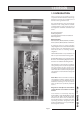
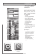
1.0 DESIGN 1.2 TECHNICAL DATA Standard Equipment The standard configuration of the BoilerMate A-Class OV is shown opposite. The Appliance Control Board (A.C.B.), mounted inside the appliance, controls the operation of the complete system. The A.C.B. is pre-wired to a terminal strip where all electrical connections terminate. It is supplied with the following factory fitted equipment:1. 2. 3. 4. 5. �� � � � � �� � � � 6. 7. 8. 9. 10. 11. 12. 13.
1.0 DESIGN ����� ������ 1.
1.0 DESIGN 1.
1.0 DESIGN 1.2 TECHNICAL DATA ����������� ����������� ��� ��������� �������� ����������� ��������� �������� ��������� ����������� ��������� �������� ����� ������ �� �� ������������ ����� ������ The 2 digit display is controlled by 2 buttons S1 and S2 The flow chart of display modes is shown below. Generally, each press of button S2 cycles the display from top to bottom and each press of button S1 cycles the display functions from left to right.
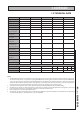
1.0 DESIGN 1.2 TECHNICAL DATA Sensor Tempature Readings Details of the various sensors S1-S6 used in the BoilerMate A-Class are shown opposite. The sensor reference i.e. S1 and the actual temperature at that sensor flash alternately on the display when selected. Sensors used in BoilerMate A-Class Sensor Sensor Connector J9 pins Location S1 T Overheat 1 6 & 14 S2 T Overheat 2 2 & 10 S3 T DHW in 3 & 11 In cold water inlet pipe (Wet i.e.
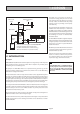
1.0 DESIGN 1.3 SYSTEM DETAILS Hot and Cold Water System General A schematic layout of the hot and cold water services in a typical small dwelling is shown below. BoilerMate A-Class will operate at mains pressures as low as 1 bar and as high as 5 bar although the recommended range is 2-3 bar. These pressures are the minimum dynamic pressures at the cold connection to the BoilerMate A-Class at the time of the maximum calculated simultaneous demand.
1.0 DESIGN 1.3 SYSTEM DETAILS Hot and Cold Water System Pipe Sizing / Materials To achieve even distribution of the available supply of hot and cold water, it is important in any mains pressure system, that the piping in a dwelling should be sized in accordance with BS 6700. This is particularly important in a large property with more than one bathroom.
1.0 DESIGN 1.3 SYSTEM DETAILS Heating System ���������� ����� ����������������� ����� General A schematic layout of the heating system in a typical small dwelling is shown opposite. ������ �������� The flow and return from the boiler must always run directly to the BoilerMate A-Class and the flow should rise continuously to facilitate venting. The heating circuit is taken from the BoilerMate A-Class and is piped in the conventional manner.
1.0 DESIGN 1.3 SYSTEM DETAILS Heating System Pipe Sizing/Materials The primary pipework connecting the boiler and the thermal store should be sized to achieve a maximum of 8°C rise across the boiler or the maximum temperature rise specified by the boiler manufacturer, whichever is smaller, but in any instance it should not be less than 22mm copper tube. Note: There should be no valves in the pipework connecting the boiler to the BoilerMate A-Class.
1.0 DESIGN 1.3 SYSTEM DETAILS Heating System Boiler sited above the BoilerMate Any boiler used must be fitted with an overheat thermostat i.e. it must be suitable for use in a sealed system. ����������������������� ������������������������ ������������� The F & E cistern must be fitted at a height which will provide the minimum head required for the boiler and must be at least 250mm above the highest point of the system.
1.0 DESIGN 1.3 SYSTEM DETAILS Heating System ������������� �������� ���������� Connection of Bathroom Radiator/ Towel-Rail for Summer use If a pumped circuit is required for the bathroom radiator/towel rail, the flow pipework can be teed anywhere into the primary flow between the boiler and the BoilerMate. The return pipework can be connected into the 15mm copper blanked connection provided adjacent to the boiler pump. We recommend any radiators/towel rails on this circuit are provided with T.R.V.
1.0 DESIGN 1.3 SYSTEM DETAILS Heating System Method of connecting two BoilerMates to one heat source. If the primary flow and return pipework continuously rises from the boiler to the BoilerMate the recommended method for connecting two BoilerMates to one heat source is to fit the BoilerMates as normal but to provide a single check valve on the branch immediately after each primary pump. The heating and hot water from each appliance must serve separate zones/bathrooms within the property.
1.0 DESIGN 1.3 SYSTEM DETAILS ����������������� ‘Switch’ ��� ������������� ��������������� �������������� �� ������ ���������������� ������������������������ �������������������� ����������� ����������� ������������������ ���� ������ �������� The BoilerMate A-Class is supplied with ‘Switch’ which provides a 6kW electrical emergency back up in the case of failure of the main heat source i.e. gas boiler. This must NOT be used to provide hot water only in summer if the main system is working correctly.
2.0 INSTALLATION 2.1 SITE REQUIREMENTS The appliance is designed to be installed in an airing/cylinder cupboard and the relevant minimum dimensions are provided in section 1.2 Technical Data. Because of the ease of installation we recommend that the cupboard construction is completed and painted before installation of the appliance. The cupboard door can be fitted after installation.
2.0INSTALLATION 2.2 INSTALLATION Preparation/placing the appliance in position. Details of the recommended positions for termination of the first fix pipework are provided in section 1.2 Technical Data. The pipework can be located or its position checked using the template provided with each appliance. If these have been followed installation is very simple and much quicker than any other system. The appliance is supplied shrink wrapped on a timber installation base.
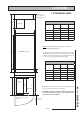
2.0INSTALLATION 2.2 INSTALLATION Pipework connections The position of the pipework connections is shown opposite. The connection sizes and dimensions are listed in Section 1.2 Technical Data. All the connections are also labelled on the appliance. It is essential that the pipework is connected to the correct connection. Connections A, B, C, E and G are plain ended copper pipe. Connections D, F and H are compression fittings. Connection I is RC½ (½ in BSPT internal). Connection J is a blanked copper pipe.
2.0INSTALLATION 2.
2.0 INSTALLATION 2.
2.0 INSTALLATION 2.2 INSTALLATION It is normally envisaged that the feed and expansion cistern will be located in the same cupboard as the BoilerMate appliance itself to maintain a dry roof space.
2.0 INSTALLATION 2.2 INSTALLATION Electrical Connection - Standard Appliance The BoilerMate A-Class OV is pre-wired to DIN rail terminals from the A.C.B. and plumbers are well able to complete the electrical installation provided they adhere strictly to the IEE Requirements for Electrical Installations BS 7671. All the terminals are suitably labelled. �� �� ��� ��� �� �� Note: Do not attempt the electrical work unless you are competent to carry it out to the above standards.
2.0 INSTALLATION 2.2 INSTALLATION The BoilerMate A-Class incorporates a pump overrun for the boiler pump and terminal L1 on the terminal strip (as shown on page 23) should only be used if the boiler requires a permanent live for another purpose. The boiler manufacturers wiring instructions should be read in conjunction with this manual. Before switching on the electrical supply check all the factory made terminal connections to ensure they have not become loose during transit.
2.0 INSTALLATION 2.2 INSTALLATION WARNING: Electrical Power Supplies - BoilerMate A-Class with Switch. THE BOILERMATE A-CLASS IS FITTED WITH AN ELECTRIC BACKUP SYSTEM ‘SWITCH’. IMPORTANT: ELECTRICIAN/INSTALLER PLEASE NOTE. THE 2 x 16A MCB’s (MCB1 and MCB2) FOR THE ‘SWITCH’ ELECTRIC BACKUP SYSTEM ARE SUPPLIED SET IN ‘OFF’ POSITION. THE GAS BOILER CAN BE COMMISSIONED WITHOUT SWITCHING THESE ON. IT IS IMPORTANT THAT THE GAS BOILER IS COMMISSIONED BEFORE TESTING OR USING EMERGENCY SWITCH FACILITY.
2.0 INSTALLATION 2.2 INSTALLATION ���������� ���������������� ��������������� ���������� ���������������� ����������������� ���������� ���������������� ������������������� Zoned heating systems BoilerMate is available in a multi-zone version for use where a property has to have its space heating zoned. Where this appliance version is to be used it is recommended that the BoilerMate is located on a raised platform in the cupboard creating a space below the appliance to locate the zoning equipment.
2 E N L 3 4 CT N L blue E 2.5mm2 2.5mm2 blue 23 24 red red blue 13 C2 E PD3 PD2 PD1 N N N 14 A2 10mm2 Neutral (N) 230V N L_1 L_2 L_3 E E A1 CH ‘switched’ live (L) Permanent Live (L) 230V SL_H HW ‘switched’ live (L) E SL_R SL_W Room stat ‘switched’ live (L) SL_B CH + HW HW OFF Boiler ‘switched’ live (L) BOILERMATE A-CLASS OV M ains supply 230V, 50Hz, 32A 10mm2 1 red 2.
2.0 INSTALLATION 2.3 COMMISSIONING Open the incoming stop valve and fill the domestic mains cold and hot water systems. Fill the whole of the primary heating system with potable water through the feed and expansion cistern. Check the water level in the feed and expansion cistern and adjust the ballvalve if necessary. Check the whole of the primary heating and domestic hot and cold distribution system, including the boiler and BoilerMate OV, for leaks.
2.0 INSTALLATION 2.3 COMMISSIONING Once the system is finally filled turn down the servicing valve for the ballvalve in the F & E cistern to the point where the warning/overflow will cope with the discharge arising from a ballvalve failure. Cleansing Hot/Cold Water System Treatment Fully flush and if necessary chlorinate the hot and cold water system in accordance with the recommendations in the Model Water Byelaws and BS 6700.
2.0 INSTALLATION 2.3 COMMISSIONING Commissioning Space Heating (a) The central heating is best commissioned when the store is hot and therefore should be carried out after commissioning the BoilerMate. (b) Move the central heating control rocker to the constant position, set heating programmer to continuous and ensure that the room thermostat is calling for heat. This will be indicated by display segments V1.3 and V1.4 being on respectively.
2.0 INSTALLATION 2.3 COMMISSIONING 10. DO ensure that the bypass valve for the heating system (if fitted) is set correctly. 11. DON’T use a combined feed and vent on BoilerMate installations. 12. DON’T use a BoilerMate on a sealed primary i.e. closed system. 13. DON’T use pipe smaller than 28mm between the boiler and the BoilerMate when the boiler rating exceeds 20kW (about 68,000 Btu/h). 14.
3.0 SERVICING 3.1 ANNUAL SERVICING No annual servicing of the BoilerMate A-Class is necessary. However, if required, the operation of the controls and a hot water performance test can be carried out when servicing the boiler to prove the appliance is working satisfactorily and within its specification. 3.2 CHANGING COMPONENTS Free of charge replacements for any faulty components are available from Gledhill during the in-warranty period (normally 12 months).
3.0 SERVICING 3.3 SHORTS PART LIST Key No.
3.0 SERVICING 3.4 FAULT FINDING Despite everyones best efforts some problems could occur and lead to complaints from the householder. Complaints can be grouped into the following three main categories:1. The system is noisy 2. Hot water service is unsatisfactory 3. Space heating is unsatisfactory The following checks should be carried out by the installer before calling the manufacturer. 1.
APPENDIX A WATER SAVINGS WATER RELATED COSTS CAN BE REDUCED BY GOOD PLUMBING PRACTICE. TAPS & MIXERS 1 1 2 1 Unregulated OVER 20 L/M Fitted with regulator 5, 6 OR 8 L/M 2 2 SHOWERS 4 FIXING OPTIONS FOR TAPS & MIXERS Unregulated 25 - 30 l/m Regulated 10 - 12 l/m Vast quantities of water are needlessly run off to waste due to Taps, Mixers and Showers discharging flow rates far in excess of the rates required for them to perform their duties.
APPENDIX B MANIFOLDS Two sets of manifolds are available as an optional extra. Each set comprises a separate hot and cold water manifold. Both are provided with a 22mm inlet connection located centrally. All outlet connections are 15mm compression. The centre to centre dimension of each branch is 55mm.
APPENDIX B The pressure loss through a flow regulator at the designated flow rate is about 1.8 bar. Therefore for the flow regulator to control the flow rate at pre-set level, the inlet pressure must be greater than 1.8 bar. If the inlet pressure is lower, the flow rate will be correspondingly less than the pre-set values. The maximum equivalent pipe lengths from the manifold to the terminal fittings can be estimated from the above information and the resistance characteristics of the pipes.
APPENDIX B The size of the distribution pipes supplying the manifold should be calculated using the method set out in BS 6700. A typical diagrammatic arrangement of a system using Manifold Type 1 is shown below. This is only meant to show the principles involved and the actual connection of fittings to the manifold will need to suit the arrangements shown on page 35.
APPENDIX C G U I D A N C E 2 N O T E S Inhibitor (Corrosion & scale protection of primary heating circuit) On filling the heating system and before the boiler is fired up, it is important to ensure the system water is treated with a suitable corrosion inhibitor, in accordance with the boiler manufacturer’s instructions.
APPENDIX D ������������������������������������� ����������� � ������������������������������������������������������������������������������������ ���������������������������������������������������������������������������� ������ � ����������������������������������������������������������������������������������� ������������ ����������� ���������� ���� ��������� ������������� ��� ��������� ������ ������������ �������������������������������������������������������������������������������� ������������
���������������������������� ��� ���� ����� ��� ��������� ����� ���� ����������� ������ ������� ������ ���� ��� ������� � ������� ��� ��� ������ ��� ������������������������������������������������������������������������������������������������������������� ������������������������������������������������������������������������������������������������������ ������ ������ ���� ���������� ��� ���� �������� ������ ���� ���� ������ ���� ���� �������� ��� ������ ����������� ��� ����������������������������� ��
����������������������������������������������������������������������������������������������������������������� ��������������������������������������������������������������������������������������������������������������� ��������������������������������������������������������������������������������������������������������� ���������������������������������������������������������������������������������������������������������������� ����������������������� �������������������������������������������