
Manual

3
HOW TO USE BELL & GOSSETT CIRCUIT SETTERS
TO PROPORTIONAL BALANCE A SYSTEM
1. Open fully all Circuit Setters on a single pump system.
2. If more than one branch circuit is used, start the balance
procedure by reading all of the flows to the units in a
branch. Each unit (coil) should have its own Circuit Setter
for flow balancing. Using Bell & Gossett RP-250B readout
probes, sequentially attach a Bell & Gossett differential
pressure readout kit to the readout valves on each Circuit
Setter Balance Valve.
3. Using side 2 of the Bell & Gossett Circuit Setter Balance
Valve Calculator, with the top hairline set on zero for the
size Circuit Setter being read, read the flow corresponding
to the pressure drop read with the readout kit.
4. Calculate the ratio of the actual flow to the design flow for
each unit in the branch. This is the proportional flow rate.
(Actual flow divide by design flow.)
5. Select the Circuit Setter with the lowest proportional flow
rate. This Circuit Setter is left in the full open position. Every
other Circuit Setter in the branch is then reset to the same
proportional flow rate.
6. If there are additional branches, repeat the steps in 3, 4 and
5 for each branch.
7. After all branches have been proportionately balanced,
measure the full open flows on the Circuit Setters installed
on the risers. Calculate the proportional ratio of each riser
Circuit Setter and select the one with the lowest proportional
ratio. This Circuit Setter is left fully open and the other riser
Circuit Setters are adjusted to this same ratio as described
in Step “5”.
8. Adjust pump flow so that circuits are receiving their design
flow. This can be accomplished by adjusting a Circuit Setter
Balance Valve installed on the pump discharge or by
changing the pump impeller size.
HOW TO USE BELL & GOSSETT CIRCUIT SETTER
BALANCE VALVES AS FLOW METERS
1. Energize the zone, circuit and/or system pump(s) as
applicable.
2. Using Bell & Gossett Model RP-250B Readout Probes,
sequentially attach a Bell & Gossett differential pressure
readout kit to the readout valves on each Circuit Setter
Balance Valve.
3. Read the differential pressure across the orifice of the
Circuit Setter Balance Valve.
4. Using Side #2 of the Circuit Setter Balance Valve Calculator,
set the hairline over the degree of closure as indicated by
the part of the red plastic knob or indicator plate parallel to
the degree of closure noted on the calibration plate, and
read actual GPM flowing through the Circuit Setter opposite
the gauge reading head loss noted in the white section of
Side #2.
NOTE:
If the system contains a liquid with a specific gravity and/or
viscosity higher or lower than that of water, apply the appropri-
ate correction factor noted in these instructions to obtain the
actual GPM for the system liquid.
WARNING: Hot water leakage can occur from
readout valves during probe insertion and during
hookup of readout kit. Follow the instruction manuals sup-
plied with readout probes and readout kits for safe use.
Failure to follow these instructions could result in serious
personal injury or death and property damage.
IMPORTANT: If a high degree of throttling of flow at pump
discharge is required, Bell & Gossett recommends that the
pump impeller be sized to produce design flow. This will
reduce electrical energy consumption.
WARNING: Hot water leakage can occur from
readout valves during probe insertion and during
hookup of readout kit. Follow the instruction manuals sup-
plied with readout probes and readout kits for safe use.
Failure to follow these instructions could result in serious
personal injury or death and property damage.
HOW TO USE BELL & GOSSETT CIRCUIT SETTER
BALANCEVALVESASANISOLATIONVALVE
1. Movetheadjustmentknoborstemuntilthepositionindica-
toralignswiththeclosedpositiononthecalibrationplate.
2. Closetheisolationvalveontheothersideoftheequipment
tobeserviced.
3. Openthedrain valveto drainthesystembetweenthe
CircuitSetterandsecondisolationvalve.
HOWTOUSETHEMEMORYSTOPFEATURE
Forsizes
1
/
2
"thru4":
1. Makethefinaldegreeofclosuresetting.
2. Loosen the memory stop locking screw in the slot on the
topoftheredknob.
3. Slidethememorystopscrewintheslot(counter-clockwise
for
1
/
2
" thru 1" sizes and clockwise for 1
1
/
4
" thru 4" sizes)
untilthescrewstops.
4. Tightenthememorystopscrew.
SERVICEINSTRUCTIONS
Periodically inspect the Circuit Setter for signs of leakage or
corrosion.
WARNING: Checkforpropersealingwhen usingas
an isolation valve. If the seat is not sealing properly
liquid will continue to flow fromthe drain valves. In this
case the Circuit Setter must be isolated from the system
andreplaced.Failuretofollowthese instructions could
resultinseriouspersonalinjury ordeathandproperty
damage.
WARNING: Corrosionorleakageareindicationsthat
theCircuitSettermustbereplaced.Failureto
follow these instructions could result in serious personal
injuryordeathandpropertydamage.
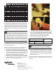
INSULATION
Bell&Gossettrecommendsthatinsulationbeattachedtothe
CircuitSetter after the systemhasbeen balanced and the
completedG95872taghasbeenwiredtotheCircuitSetter.
NOTE:
Tapeorotheracceptablemeansshouldbeusedtosecurethe
insulationtotheCircuitSetterBalanceValve.
B&GCIRCUITSETTER
CORRECTIONFACTORSFOR
VISCOSITYANDSPECIFICGRAVITY
GPM
ƒ
=
Ø
GPM
s
S.G.
√
GPM
ƒ
= ƒ GPM
s
ƒ=
Ø
S.G.
√
GPM
ƒ
– FLUID FLOW
GPM
s
– FLOW THRU SETTER
(a MEASURED CONDITIONS)
Ø – VISCOSITY CORRECTION
S.G. – SPECIFIC GRAVITY (TO WATER)