Installation, Operation, and Maintenance Manual 671075208_2.
Table of Contents Table of Contents 1 Introduction and Safety............................................................................................ 3 1.1 Introduction........................................................................................................ 3 1.2 Safety terminology and symbols..................................................................... 3 1.3 User safety.......................................................................................................... 4 1.
Table of Contents 6 Maintenance............................................................................................................ 25 6.1 Precautions.......................................................................................................25 6.2 Examine the pump.......................................................................................... 25 7 Troubleshooting......................................................................................................26 7.
1 Introduction and Safety 1 Introduction and Safety 1.1 Introduction Purpose of the manual The purpose of this manual is to provide the necessary information for working with the unit. Read this manual carefully before starting work. Read and keep the manual Save this manual for future reference, and keep it readily available at the location of the unit.
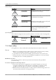
1 Introduction and Safety Hazard levels Hazard level Indication DANGER: A hazardous situation which, if not avoided, will result in death or serious injury WARNING: A hazardous situation which, if not avoided, could result in death or serious injury CAUTION: A hazardous situation which, if not avoided, could result in minor or moderate injury Notices are used when there is a risk of equipment damage or decreased performance, but not personal injury.
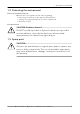
1 Introduction and Safety 1.4 Protecting the environment Emissions and waste disposal Observe the local regulations and codes regarding: • Reporting of emissions to the appropriate authorities • Sorting, recycling and disposal of solid or liquid waste • Clean-up of spills Exceptional sites CAUTION: Radiation Hazard Do NOT send the product to Xylem if it has been exposed to nuclear radiation, unless Xylem has been informed and appropriate actions have been agreed upon. 1.
2 Transportation and Storage 2 Transportation and Storage 2.1 Examine the delivery 2.1.1 Examine the package 1. Examine the package for damaged or missing items upon delivery. 2. Record any damaged or missing items on the receipt and freight bill. 3. If anything is out of order, then file a claim with the shipping company. If the product has been picked up at a distributor, make a claim directly to the distributor. 2.1.2 Examine the unit 1. Remove packing materials from the product.
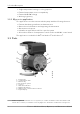
3 Product Description 3 Product Description 3.1 Product design Usage Ecocirc+ 20–18 is a wet rotor pump that uses permanent magnet and synchronous motor technology. The pump is used for systems with variable flow rates to optimize the pump operation and decrease energy consumption. Applications • • • • • Potable water system with a stainless steel body Heating for hot water Cooling for cold water Solar water heating Geothermal energy 3.
3 Product Description • • • • Single temperature heating or cooling setpoint External temperature sensor compatibility External 0–10 VDC voltage Working log history 3.2.
3 Product Description 3.4 Data plate 1 2 3 4 5 6 16 7 15 8 13 12 1. 2. 3. 4. 5. 6. 7. 8. 9. 10. 11. 12. 13. 14. 15. 16. 11 WS012667A 9 10 14 UL listing mark UL control number QR code Product name Product code Serial number Date Minimum input power Degree of protection Enclosure type Maximum input power Maximum operating pressure Maximum liquid operating temperature Maximum input current Minimum input current Input voltage range + 1 1. 2. 3. 4. 5.
4 Installation 4 Installation 4.1 Mechanical installation 4.1.1 Precautions Before starting work, make sure that the safety instructions in the chapter Introduction and Safety on page 3 have been read and understood. WARNING: Do not operate the unit in an area where explosive gases are present. WARNING: The heating of water and other fluids causes volumetric expansion. The associated forces can cause the failure of system components and the release of high-temperature fluids.
4 Installation CAUTION: CAUTION: PROPERTY DAMAGE HAZARD. It is not advisable to install circulators in an attic or upper floor over finished living space. If the circulator must be installed over head, or over expensive equipment, provide adequate drainage in the event of leakage. Failure to follow these instructions could result in property damage. CAUTION: Read this manual carefully before installing and using the product.
4 Installation WS012580A 4.1.3 Install the pump Figure 1: Correct direction of the liquid flow 1. Install the pump with new gaskets. The gaskets must be between the pipe flanges. 2 WS012581A 1 1. Gasket 2. Pump 2. Install the pump in one of the following correct positions.
4 Installation Correct Incorrect 3. Use a torque wrench to tighten the nuts on the companion flange fasteners. Fasteners Torque Companion flange fasteners 13 Nm (115 lbf.in) Union threaded ring nuts See Torque specification on page 31 4.1.4 Rotate the motor body of the pump The motor assembly of the pump can be rotated to ±90°. 1. Remove the screws from the pump body. 1 3 WS012582A 2 1. Pump body 2. Screw 3. Junction box 2. Rotate the pump housing.
WS012583A 4 Installation 3. Install the junction box in one of the following correct positions. Correct Incorrect 4. Use a torque wrench to tighten the screws of the pump body. WS012584A The torque must be 5 Nm (44 lbf.in). 4.1.5 Insulation housing 4.1.5.1 Requirements NOTICE: Improper installations shown above can cause the pump to fail prematurely and create an electrical hazard and/or damage caused by water leakage.
4 Installation • Only use the pump thermal shells that are included in the delivery. Do not insulate the motor housing, the electronics can overheat and cause the pump to thermally overload. • The thermal shells that are included with the pump must only be used in hot water circulation applications with fluid temperature above 68°F (20°C). The thermal shells are permeable to water vapor. • The pump housing must not be insulated past the motor flange.
4 Installation WARNING: Electrical Hazard Risk of electrical shock or burn. A certified electrician must supervise all electrical work. Comply with all local codes and regulations. WARNING: Electrical Hazard There is a risk of electrical shock or explosion if the electrical connections are not correctly carried out, or if there is fault or damage on the product. Visually inspect equipment for damaged cables, cracked casings or other signs of damage.
4 Installation 4.2.2 Requirements • The National Electrical Code (NEC), Canadian Electrical Code (CEC), and local codes must be followed. • If the branch circuit is fitted with a ground fault circuit interrupter, it must be applicable to use with the inverter-driven appliances. • The electrical cables must be protected from high temperature and vibration. • The current type and voltage of the power supply connection must follow the specifications on the nameplate of the pump.
4 Installation 4.2.4 I/O terminals 5 6 WS012687A 1 2 3 4 Terminal Parameter Description 1 Temp IN+ External temperature sensor input 2 Temp IN- External temperature sensor input 3 0-10V IN+ 0-10V constant speed input 4 0-10V IN- 0-10V constant speed reference 5 Not used Not used 6 Not used Not used 4.2.4.1 Control mode for water temperature Control modes for water temperature can be activated only by using the application MY ecocirc.
4 Installation Mode Description Constant pressure that depends on the water temperature, ConstΔP/T Changes the setpoint of the differential constant pressure according to the measured water temperature This mode is used in the following applications: • Uses the external temperature sensor for positive relation, P/T • Uses the external temperature sensor for negative relation, P/T • Uses the external temperature sensor for positive relation, P/T • Uses the external temperature sensor for negative relation
4 Installation Pump status 5 4 RPM MAX 10 6 7 MIN 3 9 8 10 Position 2 Vin(V) 11 11 Control voltage input (Vin), thresholds (V) Vin, increases Speed setpoint (rpm) Pump status Speed setpoint (rpm) Pump status 1 and 7 1.20 0 OFF MIN RUN 2 1.49 0 OFF MIN RUN 3 and 6 1.50 MIN RUN MIN RUN 4 and 5 10 MAX RUN MAX RUN 8 1.19 - Input is disabled 0 OFF 9 0.
5 Operation 5 Operation 5.1 Precautions Before starting work, make sure that the safety instructions in the chapter Introduction and Safety on page 3 have been read and understood. WARNING: Crush Hazard Risk of automatic restart. CAUTION: Do not exceed the maximum working pressure of the pump. This information is listed on the nameplate of the pump. 5.2 Requirements Before starting the pump, follow all the instructions in the chapter Installation on page 10. The pump must be vented fully.
5 Operation 22 Position Operating mode LED status Description Performance curve: • 1. Low • 2. Intermediate • 3. High Operation at constant pressure - This position is selected for infloor heating systems. The pressure stays constant, when the water flow is increased or decreased. Performance curve: • A. Low • B. Intermediate • C. High Operation at proportional pressure - This position is selected for twopipe heating systems. The pressure changes according to the actual demand for heat.
5 Operation 5.5 Set the night mode If the night mode is active when the power is off, it is deactivated when the power is turned on. 1. Select one of these operating modes 1, 2, 3, A, B, C, I, II, and III on the user interface. 2. Press and hold the night mode button to activate the night mode. The yellow light shows that the night mode is on. WS012617A The green light shows that the night mode is off. 3. Press and hold the night mode button to deactivate the night mode. 5.6 Reset the error 1.
5 Operation 4. Select the ecocirc+ from list of the devices that are detected in the device connectivity of the mobile phone. 5. Press and hold the night mode button on the user interface. The digital display shows the three-digit personal identification number (PIN). 6. Note the three-digit PIN. 7. Repeat the steps 5 on page 24 and 6 on page 24 to obtain the last 3 digits of the PIN. 8. Enter the six-digit PIN number into the mobile phone.
6 Maintenance 6 Maintenance 6.1 Precautions Before starting work, make sure that the safety instructions in the chapter Introduction and Safety on page 3 have been read and understood. Electrical Hazard: Disconnect and lock out electrical power before installing or servicing the unit. WARNING: • Always wear protective gloves when handling the pumps and motor. When pumping hot liquids, the pump and its parts may exceed 40°C (104°F).
7 Troubleshooting 7 Troubleshooting 7.1 Precautions Before starting work, make sure that the safety instructions in the chapter Introduction and Safety on page 3 have been read and understood. DANGER: Electrical Hazard Troubleshooting a live control panel exposes personnel to hazardous voltages. Electrical troubleshooting must be done by a qualified electrician. DANGER: Crush Hazard Moving parts can entangle or crush. Always disconnect and lock out power before servicing to prevent unexpected startup.
7 Troubleshooting LED status Error Cause Remedy E03 The supply voltage is too high. 1. Check that the grid voltage is in accordance with the rated values. 2. Reset the error. For more information, see Reset the error on page 23. 3. If the problem continues, replace the pump. E03 or E06 The regeneration effect occurs because the other equipment generates the water flow. 1. Remove the source of the flow. 2. Reset the error. For more information, see Reset the error on page 23. 3.
7 Troubleshooting LED status Error Cause E10 The protection against 1. Reset the error. dry run of motor For more information, see Reset the error on page 23. 2. If the problem continues, replace the pump. Remedy 7.4 The pump does not start The LED and the user interface are switched off. LED status Error Cause Remedy Off None The following electric safety devices are open: • System fuse • Circuit breaker of thermal magnetic device • Ground fault circuit interrupter 1.
7 Troubleshooting LED status State Wireless - Blinks fast Steady light Error Cause Remedy - The wireless function is not connected to the mobile device. Connect the wireless function with the mobile device. - The incorrect pairing of PIN the mobile device 1. Generate a new PIN. 2. Connect the mobile device. 3. Reset the error. For more information, see Reset the error on page 23. 4. If the problem continues, replace the pump. - The communication error 1. Reset the error.
7 Troubleshooting LED status Error Cause Remedy Green None Air in the pump 1. Check that the pump is not installed at the highest point of the system. 2. Start the air purge process. 3. Wait for 3 minutes to complete the air purge process. Cavitation 1. Do one of the following methods to decrease the cavitation: – Increase the system pressure according to the working limits. – Select a different operating mode. – Decrease the head speed of the pump to decrease the head 2.
8 Technical Specification 8 Technical Specification 8.1 Environmental requirements Feature Value Operating environment Non-aggressive, nonexplosive atmosphere, and no frost Operating temperature -10°C to 40°C (14°F to 104°F) Relative humidity < 95% at 40°C (104°F), non-condensing 8.2 Torque specification Joint size Pipe material Torque, Nm (lbf.ft) G1 Plastic 50 (37) G1 Cast iron 85 (63) G1¼ Cast iron 105 (78) G1½ Cast iron 125 (92) G2 Cast iron 165 (122) 8.
8 Technical Specification The pump can be used with water/propylene glycol mixtures up to 50% with a maximum viscosity of 50cST at 14°F (-10°C). The pump has built-in overload and thermal protection to protect the pump from overload due to increased fluid viscosity. Pump performance is based on 77°F (25°C). Therefore pumping of glycol mixtures will affect max performance, depending on mixture concentration and temperature. 8.6 Maximum operating pressure • 1 MPa (145 psi) 8.
9 Product Warranty 9 Product Warranty Commercial warranty Warranty.
9 Product Warranty WARRANTIES ARE LIMITED TO REPAIRING OR REPLACING THE PRODUCT AND SHALL IN ALL CASES BE LIMITED TO THE AMOUNT PAID BY THE BUYER FOR THE DEFECTIVE PRODUCT.
9 Product Warranty PARTICULAR PURPOSE, ARE LIMITED TO THIRTY (30) MONTHS FROM THE DATE OF INSTALLATION OR THIRTY-SIX (36) MONTHS FROM THE PRODUCT DATE CODE , WHICHEVER SHALL OCCUR FIRST. EXCEPT AS OTHERWISE REQUIRED BY LAW, BUYER’S EXCLUSIVE REMEDY AND SELLER’S AGGREGATE LIABILITY FOR BREACH OF ANY OF THE FOREGOING WARRANTIES ARE LIMITED TO REPAIRING OR REPLACING THE PRODUCT AND SHALL IN ALL CASES BE LIMITED TO THE AMOUNT PAID BY THE BUYER FOR THE DEFECTIVE PRODUCT.
10 Certifications 10 Certifications 10.1 FCC 15.247 The 2AYCGXSI01 is compliant to Part 15 of the FCC Rules. Operation is subject to the following two conditions: 1. This device may not cause harmful interference. 2. This device must accept any interference received, including interference that may cause undesired operation. This device has been designed and complies with the safety requirements for portable (<20cm) RF exposure in accordance with FCC rule part 2.
Xylem |’zīləm| 1) The tissue in plants that brings water upward from the roots; 2) a leading global water technology company. We’re a global team unified in a common purpose: creating advanced technology solutions to the world’s water challenges. Developing new technologies that will improve the way water is used, conserved, and re-used in the future is central to our work.