
Install Instructions
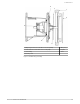
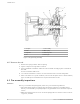
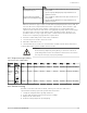
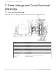
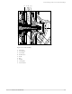
Table Of Contents

If... Then...
The motor shaft contains a dimple and
the pump shaft is keyed
1. Use a screwdriver to slide the pump side coupler over the insert as
far as possible.
2. Gap the coupler by sliding the pump coupler half back 1/16 in.
3. Tighten the setscrews
The motor shaft is keyed and the
pump shaft is either dimpled or keyed
1. Use a screwdriver to slide the motor side coupler over the insert as
far as possible.
2. Gap the coupler by sliding the motor coupler half back 1/16 in.
3. Tighten the setscrews
When an elastomeric type coupler is used with a keyed pump and/or motor shaft, do
not leave the insert compressed between the coupler halves. There must be a gap
between the ends of the insert and the coupler flanges to accommodate shaft
expansion and contraction. If the insert is not gapped, the pump and motor bearings
are subjected to excessive loads, which leads to premature failure. However, it is
possible to have too large a gap. The gap is considered excessive when the insert
teeth are not completely engaged in the coupler halves.
6. Insert the conduit and power leads on the conduit box.
7. Connect the power leads to the motor leads.
8. Install the conduit box cover.
9. Check that the motor rotation is clockwise when viewed from the back of the motor.
10.Fill and bleed the system and then check for leaks.
WARNING:
– Pressurize the pump body slowly while you check for leaks at all
joints with gaskets. Failure to follow these instructions can result in
serious personal injury or property damage.
6.3.5 Capscrew torque values
Capscrew torque in ft-lbs (Nm)
Capscrew
type
Head
marking
1/4 in. 5/16 in. 3/8 in. 7/16 in. 1/2 in. 5/8 in. 3/4 in. 7/8 in. 1 in.
SAE grade 2 6 (8) 13 (18) 25 (34) 38 (52) 60 (81) 120 (163) 190 (258) 210 (285) 300 (407)
Brass or
stainless
steel
or
4 (5) 10 (14) 17 (23) 27 (37) 42 (57) 83 (113) 130 (176) 200 (271) 300 (407)
SAE grade 5 10 (14) 20 (27) 35 (47) 60 (81) 90 (122) 180 (244) 325 (441) 525 (712) 800 (1085)
6.3.6 Dealer servicing
If trouble occurs that cannot be rectified, contact your local sales and service
representative and be prepared to provide this information:
1. Complete nameplate data of pump and motor
2. Suction and discharge pipe pressure gauge readings
3. Ampere draw of the motor
4. A sketch of the pump hook-up and piping
6 Maintenance
Series e-60 INSTRUCTION MANUAL 23