
User Guide

PERIODIC INSPECTION
Bell & Gossett Booster Pumps are designed to provide years
of trouble free service. It is recommended that periodic in-
spections be made to check for potential problems with the
PERIODIC INSPECTION
pump. If any leakage or evidence of leakage is present repair
or replace the unit.
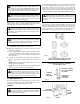
FIG. 5
REAR
BEARING
CONDUIT BOX
SHAFT SLEEVE
PUMP BODY
BODY GASKET
COVER PLATE ASM
IMPELLER ASM
W/THREADED HUB
SEAL ASM
FRONT BEARING
HOUSING/STATOR ASM
SHAFT/ROTOR ASM
Reposition the face plate on the motor housing. Gently
tap the face plate evenly around its diameter to drive it
into the recess provided in the motor housing.
18. Clean the shaft and sleeve before installing the new seal.
19. Slide the new carbon seal head onto the shaft sleeve until
it contacts the seal seat. Slide the new “O-Ring” and
back-up ring along the shaft sleeve until they fit inside the
counter bore in the seal head. Place the seal spring
between the back-up ring and the seal cage while posi-
tioning the seal cage flush with the end of the sleeve.
Place the small end of the spring against the back-up ring.
The three driving legs of the seal cage should engage the
three slots on the seal head. While holding the rotor
assembly with the screwdriver, thread the impeller onto the
shaft in a counter clockwise direction. Tighten the impeller
with light hand pressure. Take care to avoid bending a
rotor cooling fin or damaging the shaft sleeve.
10. Clean the recess in the pump body and install a new body
gasket.
11. Install the pump in the body and secure with four cap-
screws. Apply torque evenly in a criss cross pattern in 40
in-lb (4.52 N
•
m) increments to a torque of 80 in-lb (9.04 N
•
m).
12. Reinstall into the system using new flange gaskets. For
instructions, see sections “PUMP INSTALLATION” and
“WIRING INSTRUCTIONS” on pages 2 and 3.
INSTRUCTIONS FOR REPAIRING
MECHANICAL SEAL
11. Follow steps 1 through 4 of section titled “REMOVAL OF
PUMP FROM EXISTING SYSTEM FOR REPLACEMENT.”
12. Loosen the four capscrews that hold the motor housing to
the pump body. Remove these screws and remove the
housing from the pump body.
13. Place the pump on a flat work surface and insert a screw-
driver into one of the endplate ventilation slots until it
engages one of the rotor cooling fins. While holding the
rotor with the screwdriver, turn the impeller clockwise.
Note that the impeller is molded around a metal hub with a
left hand thread. Remove the impeller from the shaft.
14. Remove the seal assembly from the shaft by sliding it off
the shaft sleeve.
15. Clean the seal seat with a clean rag and inspect for groov-
ing or cracks. If it shows no grooving or cracks, it may be
cleaned and reused.
16. If the seal seat is to be replaced, the face plate must be
removed from the motor housing. Remove it by gently pry-
ing it away from the housing.
17. Remove the seal seat and cup. Lubricate the cup with
soapy water and install new parts in the face plate recess.
SEAL
CAGE
SEAL
SPRING
BACK-
UP
RING
O-RING
CARBON
SEAL HEAD
SEAL
SEAT
SEAL
CUP
Packaged together
as an assembly
SEAL
COMPONENTS
ITT
8200 N. Austin Avenue
Morton Grove, IL 60053
Phone: (847) 966-3700
Fax: (847) 966-9052
www.bellgossett.com
© COPYRIGHT 2007 BY
ITT CORPORATION
PRINTED IN U.S.A. 12-07
THE ITT ENGINEERED BLOCKS SYMBOL AND
ENGINEERED FOR LIFE ARE REGISTERED
TRADEMARKS OF ITT CORPORATION